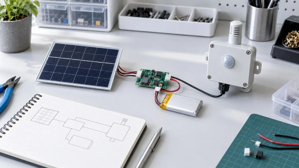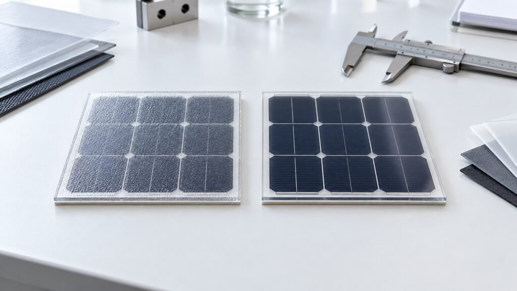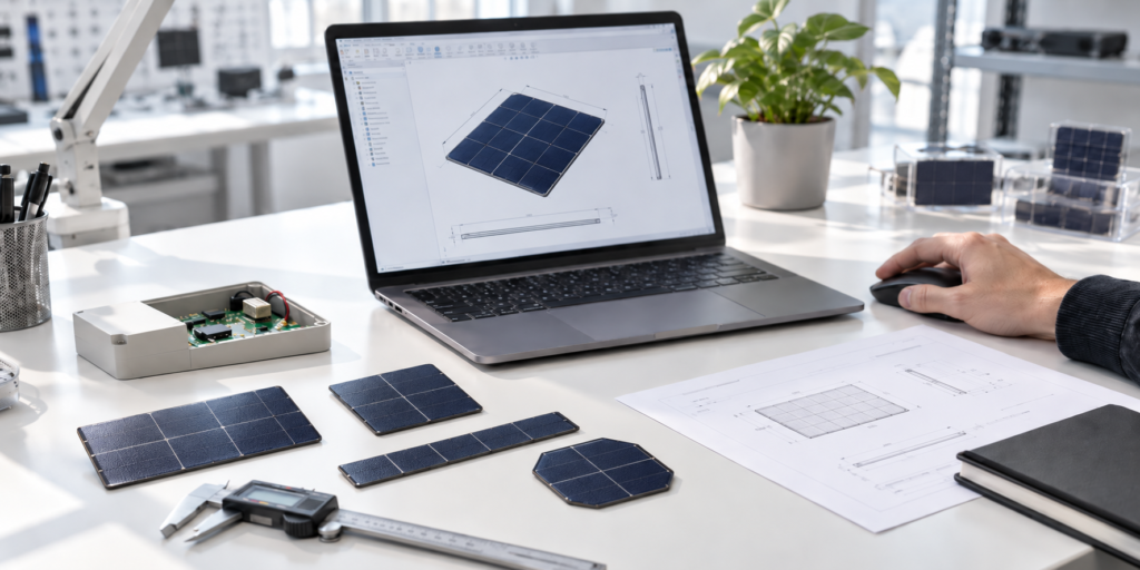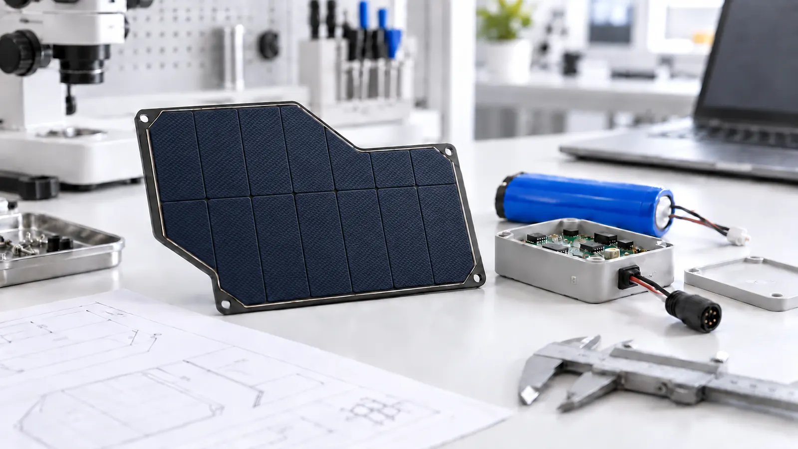
A custom monocrystalline solar panel is useful when a standard module cannot meet a product’s available area, voltage window, mounting method, or environmental requirements. The design task is not simply to cut a conventional panel into a smaller rectangle. Cell layout, laminate construction, electrical matching, cable routing, and product integration must be considered together.
This guide explains how OEM product teams can define a compact monocrystalline module for sensors, trackers, cameras, portable electronics, and other embedded systems.
What Is a Custom Monocrystalline Solar Panel?
A monocrystalline solar cell is made from single-crystal silicon. In a custom module, those cells are cut and interconnected to create the required footprint and electrical output. The cells are then protected by a material stack selected for the product’s environment and mechanical design.
Customization can include the outside dimensions, shape, active cell area, voltage, current, surface material, backing structure, cable length, connector, mounting features, and appearance. The resulting module should be treated as part of the product architecture rather than as a separate accessory.
When Does a Product Need a Custom Module?
A standard panel is often the lowest-risk choice when its dimensions and electrical characteristics already fit the system. Custom development becomes practical when one or more constraints cannot be resolved with a catalog part.
- The enclosure provides a fixed or irregular installation area.
- The charging circuit needs a voltage not available from standard modules.
- The product requires a particular connector, cable exit, or polarity.
- Weight or thickness must be controlled.
- The panel must conform to a gentle fixed curve.
- The surface finish must match the industrial design.
- Outdoor exposure requires a more suitable laminate and sealing approach.
- The module must be repeatable from prototype through production.
For compact electronics, the available surface area frequently sets the upper limit on useful output. A supplier can optimize the cell layout, but customization cannot create energy that the available light and active area cannot provide.
Start With the Device Energy Budget
Before choosing dimensions or wattage, calculate how much energy the device uses during a complete operating cycle. Include sleep current, sensing, processing, wireless transmission, display updates, actuators, indicators, and losses in the power path.
Peak current and daily energy answer different questions. The battery and power electronics must support short current peaks, while the solar module must replace the energy used over time. For a detailed calculation workflow, use the existing guide on how to size a solar panel for an IoT device.
Define the lowest practical light conditions for the target installation. Outdoor output varies with season, orientation, temperature, cloud cover, dirt, and shading. A nameplate rating alone does not predict daily energy in the finished product.
Define the Available Area and Shape
Provide the maximum length and width, corner radius, thickness limit, keep-out zones, and the location of any holes or cutouts. Mark which area can contain active cells and which area is reserved for sealing, mounting, or cable routing.
Irregular shapes can help a module fit around sensors, antennas, displays, fasteners, or housing features. However, every cutout or narrow section can reduce active area and complicate the cell layout. An early drawing is more useful than a general request for a small panel.
Match Voltage to the Charging Electronics
The module voltage should be selected around the input requirements of the charging circuit or power-management IC, not only the battery’s nominal voltage. Share the charging IC model, input operating range, absolute input limit, preferred operating point, battery chemistry, and series-cell configuration.
Solar cells connected in series increase voltage. Parallel paths increase current. The final arrangement must fit inside the permitted area while leaving suitable space for interconnection and edge protection. Review maximum-power voltage, open-circuit voltage, maximum-power current, and short-circuit current as a set.
Select the Module Construction
The outer material and backing structure affect weight, appearance, durability, and mechanical behavior. Common options for compact modules include ETFE-based lightweight laminates, PET-based constructions for more protected applications, and glass-front modules for rigid products.
Material names alone do not define field performance. Encapsulant, backsheet, adhesive, edge design, cable exit, manufacturing process, and installation method also matter. The ETFE versus PET comparison explains how to evaluate two common lightweight surfaces.
Rigid construction
A rigid module may be appropriate when the product provides a flat mounting surface and values dimensional stability, clean appearance, or physical protection. The supporting substrate and mounting method should be included in impact and vibration testing.
Lightweight or semi-flexible construction
A lightweight laminate can reduce thickness and weight or conform to a gentle fixed curve. It should not be assumed to tolerate repeated bending. The cells and interconnections still have mechanical limits, so the approved bend radius and installation process must be defined.
Plan the Cable, Connector, and Mounting Method
Small integration details frequently create late design changes. Specify cable type, length, exit position, strain relief, connector part number, mating connector, polarity, and any exposed wire requirement. Confirm whether the cable exits from the front, rear, or edge and whether that direction interferes with the enclosure.
Mounting options can include pressure-sensitive adhesive, mechanical fasteners, brackets, pockets, stitching into a textile assembly, or integration behind a product window. Test the actual adhesive and substrate because surface energy, temperature, moisture, and assembly pressure affect bond performance.
Account for Partial Shading
Antennas, handles, enclosure edges, nearby structures, and the product’s installation angle can cast narrow shadows. A small shadow can affect current through a series-connected cell string. Show the supplier the likely shadow direction and any permanently obstructed area before the electrical layout is finalized.
Prototype testing should include realistic orientations and partial-shading cases rather than only direct, uniform illumination.
Move From Drawing to Production
A practical development process includes requirement review, preliminary drawing, electrical proposal, material selection, sample production, product-level testing, design revision, approved specification, pilot production, and production inspection.
Use revision-controlled drawings and identify which sample represents the approved appearance and construction. Define measurable acceptance criteria for dimensions, polarity, electrical output, connector assembly, surface appearance, and packaging.
Validation should reflect the final application. Depending on the product, useful checks may include dimensional inspection, controlled electrical measurement, charging tests, adhesion, vibration, bending, temperature cycling, humidity exposure, UV exposure, water-related tests, and repeated installation handling. Do not assign a certification or protection rating until the complete product has been evaluated through the appropriate process.
Information to Send With an RFQ
- Product application and operating environment
- Maximum module dimensions, shape, and thickness
- Target voltage, current, power, or daily energy
- Battery and charging-circuit information
- Expected light conditions and installation orientation
- Surface, substrate, and appearance preferences
- Cable, connector, polarity, and cable-exit position
- Mounting method and enclosure drawing
- Prototype quantity and forecast production volume
- Application-specific test requirements
Frequently Asked Questions
Can a monocrystalline solar panel be made in a custom shape?
Yes. The outside laminate and cell layout can be developed for non-standard shapes, but cutouts and narrow areas reduce the space available for active cells.
Is monocrystalline silicon always the best choice for a compact product?
It is a strong option when outdoor power density and limited area are important. The final choice should also consider light conditions, appearance, cost, construction, and production requirements.
Can the panel voltage be customized?
Yes. Voltage can be adjusted through the cell arrangement, within the physical limits of the available area and the selected cell format.
Can a small panel charge a lithium battery directly?
No. The system requires an appropriate charging and protection circuit matched to the battery and solar source.
What determines the minimum panel size?
The required energy, available light, cell performance, system losses, voltage configuration, and inactive border area all influence the minimum practical dimensions.
Develop the Module Around the Product
A successful custom monocrystalline solar panel begins with measured device consumption, realistic light assumptions, a clear enclosure drawing, and complete power-electronics information. These inputs allow the module, battery, charging circuit, and mechanical design to be evaluated as one system.
Review SiborTech’s small custom solar panel capabilities and application examples. When your basic requirements are ready, discuss your custom solar project with the engineering team.