To size a solar panel for an IoT device, start with energy balance rather than a nominal wattage. A wireless sensor may draw high current for a few seconds during measurement or transmission, then remain in sleep mode for hours. The solar panel, charging circuit, and battery must support the complete operating cycle under realistic light conditions.
This practical method helps product teams estimate a starting panel size and identify the data needed before prototyping.
Step 1: Calculate Daily Energy Consumption
List every operating state of the device, including sleep, sensing, processing, wireless transmission, display activity, GPS acquisition, and any heaters or actuators. For each state, multiply power by operating time.
Daily energy = Power × Time
If current is easier to measure, use:
Energy (Wh) = Voltage × Current (A) × Time (hours)
Add the energy used by all states over 24 hours. Measured data from the real hardware is more reliable than values copied from component datasheets because firmware, signal strength, sensors, and voltage regulators affect consumption.
Example duty cycle
Consider a 3.3V sensor node that sleeps most of the day, wakes every 15 minutes, takes a measurement, and sends data through a LoRa radio. Its transmission current may be much higher than its sleep current, but transmission lasts only a short time. The average daily energy can therefore remain low.
Do not size the panel from peak current alone. The battery supplies short peaks; the solar system must replace the total energy used over time.
Step 2: Include Conversion and Charging Losses
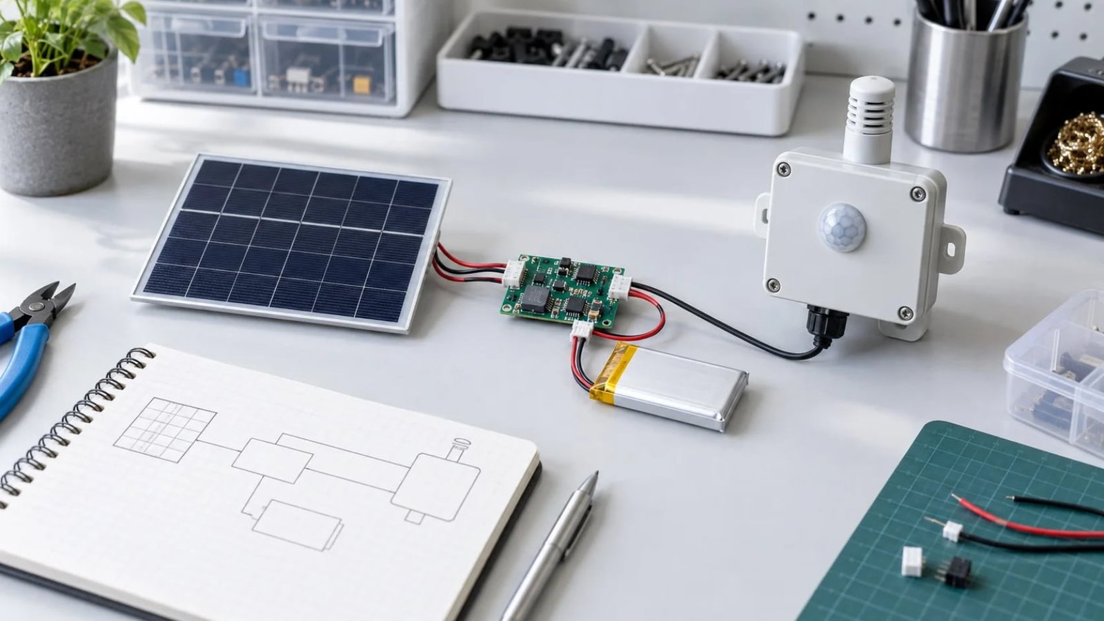
Energy passes through the charging circuit, battery, and voltage regulators before reaching the load. None of these stages is perfectly efficient. Cable losses, temperature, battery age, and standby consumption also reduce usable energy.
For an early estimate, divide the load energy by an assumed system efficiency rather than treating panel energy and device energy as equal. The final factor should be confirmed through testing with the actual power electronics.
Required solar energy = Daily load energy ÷ System efficiency
Step 3: Define the Real Light Environment
A panel’s rated power is measured under controlled test conditions. Field output can be lower because of panel angle, temperature, dirt, cloud cover, shading, enclosure windows, and seasonal changes.
Define where the device will operate:
- Open outdoor sunlight
- Urban locations with buildings or trees
- Under a canopy or translucent cover
- Inside a vehicle or behind glass
- Warehouse, retail, office, or home lighting
- High-latitude or strongly seasonal climates
For outdoor projects, use the lowest practical solar resource for the target season rather than an annual best-case average. For indoor devices, measure the expected illuminance and light spectrum at the actual installation point. Indoor photovoltaic output cannot be estimated accurately from outdoor watt ratings.
Step 4: Estimate the Required Panel Power
A simplified outdoor estimate is:
Panel power = Required daily solar energy ÷ Effective sun hours
Then apply a design margin for weather variation, installation tolerances, aging, and uncertainty in the load estimate. The appropriate margin depends on the consequence of downtime and how often the site can be serviced.
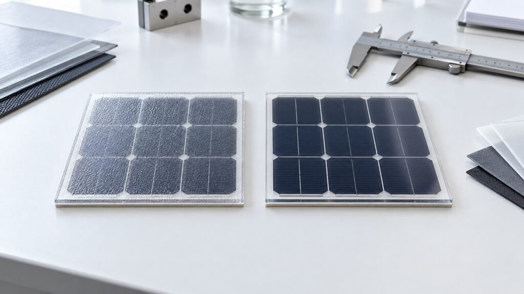
For indoor energy harvesting, work from measured power density under the target light source. Multiply the available active area by the measured output per unit area, then compare it with the device’s daily energy requirement. Rigid indoor perovskite solar panels are one integration route for low-light sensors and connected devices.
Step 5: Check Whether the Available Area Is Large Enough
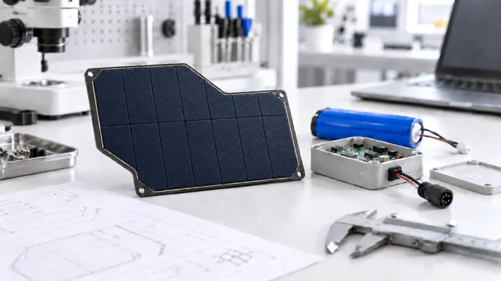
Panel power is limited by active cell area and conversion efficiency. If the enclosure provides only a small surface, the desired output may not be physically achievable. A small custom solar panel can be configured around the available dimensions, target voltage, current, connector, and mounting method, but it cannot overcome an inadequate light or area budget.
When space is limited, the engineering team can consider:
- Reducing transmission frequency
- Improving sleep-mode current
- Using a lower-power communication protocol
- Optimizing antenna performance to shorten transmissions
- Increasing the battery reserve
- Using higher-efficiency cells
- Moving the panel to a better-lit surface
- Increasing the available panel area
Energy optimization on the electronics side often reduces solar-panel size more effectively than searching for a marginally higher-efficiency module.
Step 6: Select the Panel Voltage for the Charging Circuit
The panel voltage must match the charging circuit’s input range with enough operating margin under expected temperature and light conditions. It should not be selected only from the battery’s nominal voltage.
Provide the solar-panel manufacturer with the charging IC model, minimum and maximum input voltage, preferred operating voltage, battery chemistry, series-cell configuration, and any maximum input limits.
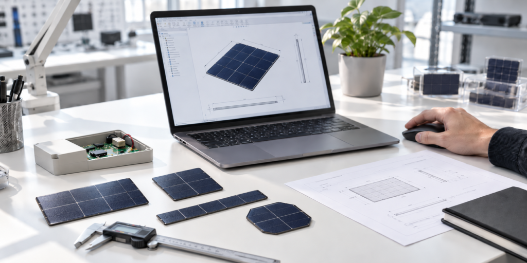
A custom cell layout can adjust voltage and current within the available area. However, increasing voltage by connecting more cell segments in series can change current and layout efficiency, so all three parameters must be reviewed together.
Step 7: Size the Battery for No-Sun Autonomy
The battery must operate the device when solar input is unavailable. Define the required autonomy period—such as three, five, or seven days—and calculate the energy needed over that period.
Battery sizing should also account for allowable depth of discharge, low-temperature performance, aging, self-discharge, and power-conversion losses. The battery must supply peak current without excessive voltage drop.
A larger battery improves autonomy, but it does not solve a long-term energy deficit. Average harvested energy must still equal or exceed average consumption over the design period.
Step 8: Consider Shading and Installation Orientation
Small products are often installed vertically, placed under covers, or partially shaded by the product itself. A narrow shadow can reduce output more than expected depending on cell interconnection.
Review panel orientation, likely shadow direction, cable position, mounting method, and whether the user can install the product incorrectly. If unavoidable shading exists, the cell layout may be optimized around the geometry.
Step 9: Prototype and Measure the Complete System
Calculations provide a starting point. Validation should use the real panel, enclosure, charging electronics, battery, firmware, and communication pattern.
Measure panel voltage and current, battery state of charge, daily energy harvested, daily load energy, charging time, overnight voltage change, and performance during several low-light days. Outdoor testing should cover representative weather; indoor testing should use the actual lamp type and placement.
Information to Prepare for a Custom Panel Supplier
- Maximum panel length, width, thickness, and shape
- Device voltage and measured daily energy
- Peak current and duty cycle
- Battery chemistry, capacity, and configuration
- Charging-circuit model and input range
- Operating location and light conditions
- Required autonomy days
- Cable, connector, mounting, and sealing requirements
- Prototype quantity and annual forecast
Frequently Asked Questions
Can I size the panel from battery capacity?
Battery capacity alone is not enough. You also need daily device consumption, charging losses, light availability, and the required recovery time after low-sun periods.
Should I use peak current or average current?
Use total daily energy for panel sizing and peak current for battery and power-path verification.
How many no-sun days should I design for?
It depends on climate, maintenance access, and the cost of downtime. Remote or critical devices usually need more reserve than easily serviced products.
Can the panel charge a 3.7V lithium battery directly?
No. A suitable charging and protection circuit is required, and the panel voltage must be matched to that circuit.
Is indoor panel sizing the same as outdoor sizing?
No. Indoor light is far weaker and has a different spectrum. Use measured indoor power density under the actual lighting conditions.
Turn the Estimate Into a Verified Design
A dependable solar-powered IoT product comes from balancing load energy, panel output, battery reserve, electronics efficiency, and the installation environment. Start with measured consumption, use conservative light assumptions, and validate the complete system before production.
Review SiborTech’s solar application examples, then share the available panel area, measured load profile, charging circuit, battery configuration, and light environment. Discuss your IoT solar project with the engineering team before prototyping.