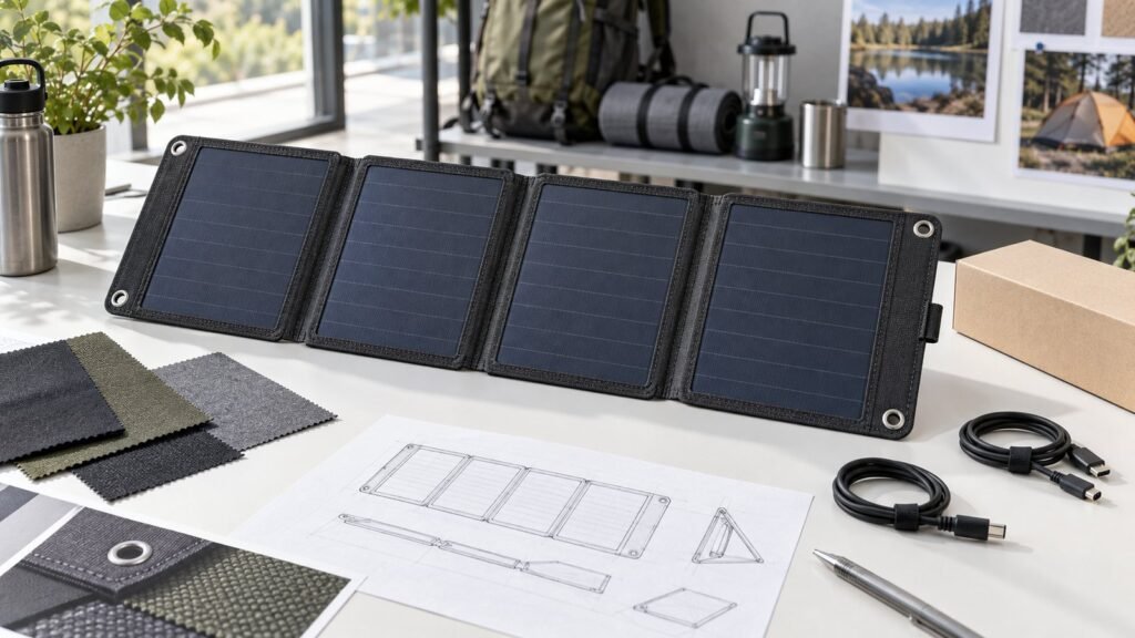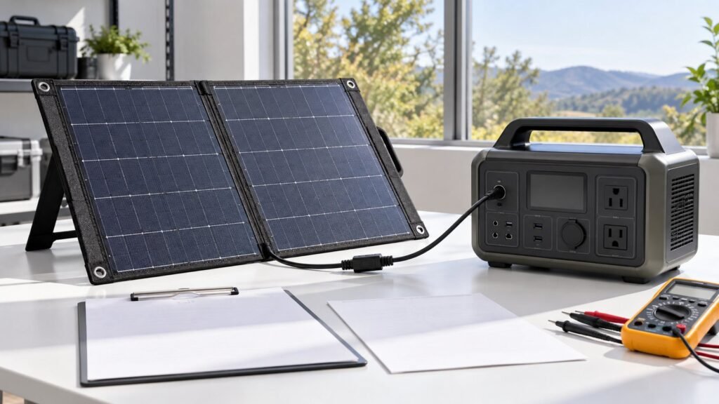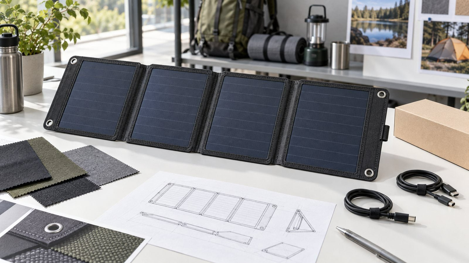
Selecting an OEM portable solar charger by wattage alone leaves many product decisions unresolved. The charger also needs to pack well, deploy quickly, connect to the intended equipment, tolerate field handling, and fit the brand’s accessory system.
A useful development brief begins with the use case. Power, panel construction, folding structure, ports, cable storage, attachment points, and packaging can then be designed around the same product goal.
Define the Primary Use Case
A hiking charger and a camping panel solve different problems.
For hiking, the buyer may prioritise low packed weight, a compact folded size, attachment to a backpack, and charging small electronics. Our foldable solar chargers for hiking cover compact power classes for portable outdoor charging.
For camping, RV, emergency, or portable power station use, the product may need a larger collection area, higher-power output, stable ground deployment, and more substantial cable management. See our foldable solar chargers for camping.
Do not combine every use case into one brief. A product optimised for a backpack is unlikely to use the same structure as a panel intended to recharge a large power station at camp.
Choose a Power Class From the Load
Start with the target equipment and charging input, not a marketing number. Record:
- Devices or power stations to be supported
- Required voltage and current range
- Charging protocol, where applicable
- Connector and polarity
- Typical energy requirement
- Expected charging window
- Deployment orientation and likely shading
- Cable length and loss constraints
Nameplate power is measured under defined conditions. Field output changes with sunlight, angle, temperature, shading, surface condition, and conversion losses. Product claims and charging-time estimates should therefore be based on verified test conditions.
Balance Open Size and Folded Size
The open panel needs enough collection area for the electrical target. The folded product needs to fit a backpack, storage compartment, or accessory case.
Panel count, fold direction, hinge width, cable position, handle placement, and connector storage all affect the packed form. A compact fold is not useful if the cable is pinched or the ports press against the active surface.
Create both open and folded drawings. Include thickness, hinge allowance, edge construction, handle, pockets, closures, feet or supports, and clearance for cables.
Select the Panel and Surface Construction
ETFE is commonly considered for lightweight portable modules because it can support a textured, outdoor-oriented surface construction. Material selection should still be based on the complete laminate and application, not the surface name alone.
Review:
- Front surface and texture
- Cell and interconnect protection
- Backing stiffness
- Edge and seam design
- Fold-zone construction
- Cleaning and abrasion exposure
- Product weight and packed thickness
- Expected temperature, moisture, and UV conditions
Do not claim an IP rating, service life, or environmental certification unless it applies to the exact finished product and has supporting evidence.
Design the Folding Structure for Real Handling
Fold lines should guide the user without repeatedly bending active cell areas or stressing cable connections. The structure needs to control where the product folds and how the panels align when packed.
Prototype checks should include opening and closing sequence, cable clearance, connector storage, closure security, carrying comfort, panel-to-panel contact, and the risk of dirt or hard objects pressing against the surface.
If the product uses fabric, handles, eyelets, magnets, hooks, or buckles, specify the material and attachment method. These details affect both durability and the user’s deployment routine.
Define the Output Architecture
The output can be a direct DC connection, USB interface, USB-C solution, or another project-specific system. A port name does not define the complete behaviour.
For each output, document:
- Voltage and current behaviour
- Supported charging protocol
- Port controller or conversion architecture
- Connector and pinout
- Cable and adapter scope
- Protection and reverse-current requirements
- Operating behaviour under changing sunlight
- Indication or status features, if needed
If USB-C or USB Power Delivery is included, the design should follow the relevant specifications and component-vendor guidance. Do not assume that a USB-C connector alone provides a particular voltage or power mode.
Plan Cable and Accessory Storage
Loose cables are easy to lose and can damage the folded panel if stored poorly. Consider whether the product needs a fixed lead, removable cable, zippered pocket, elastic retainer, adapter set, or labelled accessory pouch.
The storage feature should be tested with the final cable diameter, connector body, and adapter set. Check whether it changes folded thickness or places pressure on the cells.
Add Attachment and Deployment Features Deliberately
Attachment points should reflect how the customer will use the product. Backpack loops, hanging eyelets, kickstands, vehicle attachment, or ground anchors create different loads and shadow patterns.
Map each attachment feature against the active panels. A strap or handle that shades a cell section during normal use can reduce useful output. Test likely orientations instead of evaluating only a perfectly flat, unshaded panel.
Prototype the Complete Product
An electrical sample on a bench is not enough. The OEM prototype should include the intended fold structure, output module, cables, closures, attachment points, and carrying method.
Useful field-oriented checks include:
- Open and folded dimensions
- Product weight and handling
- Deployment time and stability
- Electrical behaviour with target devices
- Restart after passing clouds or temporary shade
- Cable reach and strain relief
- Port accessibility
- Backpack or campsite attachment
- Folding sequence and surface contact
- Packing, transport, and accessory retention
Record sunlight and setup conditions during electrical tests. A result without conditions is difficult to compare.
Branding, Labels, and Packaging
OEM requirements may include colour, logo placement, labels, manuals, adapters, carrying cases, and packaging. Confirm which elements are cosmetic and which are controlled functional parts.
Labels should not cover active areas, fold lines, ventilation, or required product information. Packaging should protect the panel and connectors without forcing an unnatural fold.
Information for an OEM RFQ
| Area | Information to provide |
|---|---|
| Use case | Hiking, camping, RV, emergency, or power-station charging |
| Target equipment | Device and charging-input specifications |
| Power class | Required electrical target and test basis |
| Form factor | Open size, folded size, weight, and panel count priorities |
| Construction | Surface, backing, fabric, seams, and fold concept |
| Output | Ports, protocols, DC connector, polarity, and adapters |
| Deployment | Handles, eyelets, supports, straps, or hanging method |
| Branding | Colour, logo, labels, instructions, and packaging |
| Validation | Target devices, field scenarios, and acceptance criteria |
| Commercial | Prototype quantity, forecast, target market, and schedule |
Common Development Mistakes
Choosing wattage before identifying the target device
Compatibility depends on voltage, current, protocol, connector, and operating conditions.
Treating the folded product as an afterthought
Folds, cable storage, closures, and connector position shape the whole design.
Testing only in perfect sun
Users encounter changing orientation and partial shade. Test recovery and practical deployment.
Adding USB-C without defining the protocol
The connector shape does not define charging behaviour.
Finalising branding before functional layout
Logos, pockets, straps, and labels can interfere with active area and folds.
FAQ
What information does an OEM portable solar charger supplier need?
Provide the use case, target devices, electrical input requirements, desired power class, open and folded dimensions, ports, connectors, attachment features, branding, and expected quantity.
Can one foldable charger serve both hiking and power-station use?
There may be overlap, but weight, area, output, cable, and deployment priorities differ. Define the primary use case before combining requirements.
Does ETFE determine the finished charger’s durability?
No. Surface material is one part of the construction. Lamination, backing, edges, folds, seams, cable exits, and assembly quality also matter.
Should charging time be placed in the specification?
Only when the device, battery state, sunlight, orientation, losses, and test method are defined. Avoid a universal charging-time promise.
Next Step
If you are developing a branded portable solar product, discuss your portable solar project with us. Share the target equipment, power class, port requirements, folded-size goal, deployment method, and branding scope so the team can review the product architecture before prototype development begins.