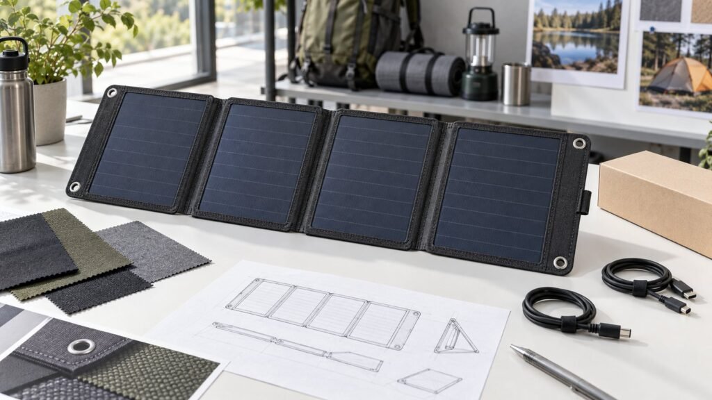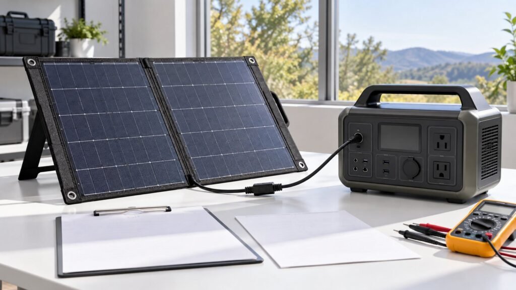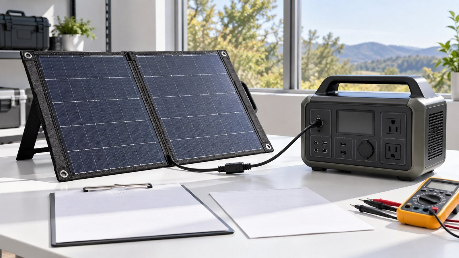
A longer cable can make a portable panel easier to place in sunlight while the power station stays in shade. That convenience has an electrical cost. Portable solar panel cable length affects the resistance of the complete outgoing and return path, so the voltage reaching the input device can be lower than the voltage measured at the panel.
The correct length is a system choice. A short cable with a poorly placed panel may collect less energy than a longer cable that allows better orientation. The aim is to test both placement and electrical loss for the intended product, not to declare one universal maximum length.
Calculate the full loop, not one conductor
Current travels to the device and returns. For a simple two-conductor cable, approximate the loop resistance from the resistance per metre of each conductor, both conductor lengths, and any connectors or adapters. Under a given operating current, voltage drop is approximately current multiplied by loop resistance. Cable heating increases with current squared multiplied by resistance.
For illustration only, if the complete loop plus connectors measures 0.8 ohm and the panel is delivering 3 A, the drop is about 2.4 V and the cable loss about 7.2 W. The example is not a recommended cable specification: real resistance depends on conductor size, material, temperature, crimps and the chosen connector system.
Ask the supplier for conductor cross-section, material, measured loop resistance, current rating and connector contact-resistance information. The custom solar cable and connector guide covers pinout, polarity and interface control. This article concentrates on the effect of length in a portable system.
Check the receiver’s input window
A power station or charge controller has voltage and current limits. The panel’s operating voltage must reach the device inside its accepted window after cable drop, including lower-light conditions. At the other extreme, cold-weather open-circuit voltage must remain within the receiver’s maximum input rating. A connector that physically fits does not prove electrical compatibility.
The portable panel–power station matching guide covers the input-window check. When adding an extension, include every adapter in the measured path. The voltage measured with no load can look normal even when a high-resistance joint causes a large drop under charge current.
Evaluate the field arrangement
Lay out the expected campsite, vehicle or outdoor-work setup. Where will the panel stand, and where will the power station remain protected? How will users coil unused cable, keep connectors out of standing water, and avoid trip or abrasion points? A long cable should not become an unplanned strain relief for the panel’s output port.
For an OEM accessory, define the supplied cable length, optional extension lengths and compatible devices. If users may connect multiple panels, review the array voltage and current separately; a longer cable is not a cure for an unsuitable series or parallel configuration.
Test at operating current
Use the actual panel, cable and receiver under recorded light. Measure voltage and current at the panel connector and at the receiver input at the same time. Compare several cable lengths under similar conditions, and repeat after connector cycling and a representative handling test. If conditions change quickly, use a controlled source or repeat the sequence to avoid mistaking a cloud for cable loss.
Inspect crimp quality, polarity, heat rise and contact protection. Retain the measured results with the cable and connector revision. If loss is excessive, options include a shorter run, a larger conductor, fewer adapter joints, or a different compatible panel/input architecture. Each option needs its own fit and safety review.
For an OEM portable panel, share the intended receiver and deployment layout with SiborTech. The cable can then be specified as part of the panel system rather than as a generic accessory.