A solar panel for a GPS tracker must support more than an average current figure. GNSS acquisition, cellular or LPWAN transmission, poor signal conditions, sleep behavior, battery recovery, enclosure area, and vehicle or container orientation all influence the energy balance.
For OEM asset-tracking products, a small custom monocrystalline panel can extend service intervals when the module, electronics, firmware, and installation environment are designed together.
Start With the Tracker’s Operating Profile
Measure the energy used during sleep, wake-up, GNSS acquisition, sensor reading, data processing, network registration, transmission, retries, and status indication. A tracker may draw little power most of the time but consume significantly more during location acquisition or communication.
Do not size the panel from peak current alone. The battery supplies short peaks; the solar module must replace total energy over the operating period. Use measurements from real hardware and production-intent firmware.
Account for Reporting Frequency
A device reporting once per day has a different energy budget from one reporting every few minutes. Geofence events, motion detection, tamper alarms, temperature logging, and over-the-air updates can add irregular loads.
Define normal, high-activity, and fault cases. If the network is unavailable, repeated connection attempts may consume more energy than normal reporting. Firmware should limit retries and adapt the reporting schedule when storage energy is low.
Communication technology changes the load profile: cellular and LoRa devices have different connection and retry behaviour, while satellite links may require longer acquisition windows and higher transmission energy. Measure the exact modem and network configuration used in the product.
Characterize the Installation Environment
Asset trackers can be installed on truck roofs, trailers, shipping containers, pallets, rail equipment, livestock devices, or stationary field assets. Each location creates different light and shading conditions.
- A horizontal vehicle roof may receive strong sunlight but high temperature.
- A container side may spend long periods facing away from the sun.
- A pallet tracker may be covered during transport.
- A livestock device may face dirt, impact, and changing orientation.
- A cold-chain tracker may move between indoor and outdoor environments.
Use the minimum realistic exposure for the deployment route, not a best-case outdoor estimate.
Define No-Sun Autonomy
The battery must operate the tracker during nights, warehouse storage, covered transport, bad weather, and periods when the panel faces an unfavorable direction. Choose an autonomy target from the real logistics cycle and the cost of losing visibility.
A larger battery extends dark-time operation but also requires more energy to recover. Average harvested energy must exceed average consumption over the design period.
Fit the Panel to the Enclosure
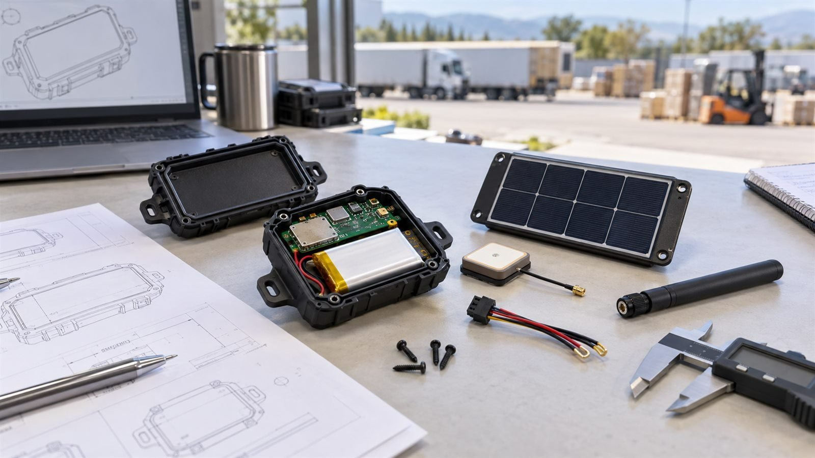
Tracker housings often reserve their largest surface for the antenna, label, mounting hardware, or impact protection. The solar module must avoid detuning antennas and should not be shaded by enclosure walls or brackets.
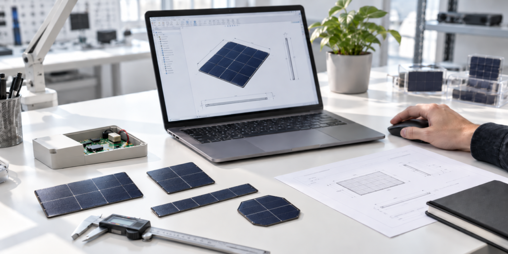
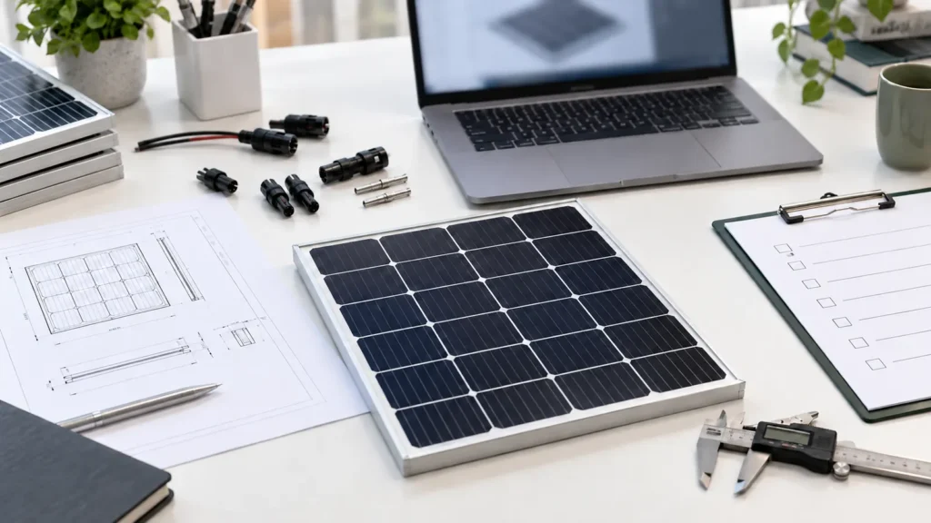
Provide a drawing with the active-area priority, antenna keep-out zone, screw locations, cable path, and curvature. A custom small solar panel can be configured around the permitted footprint and voltage target.
Select Voltage for the Charging Circuit
The panel voltage should match the charger’s useful input range across temperature and light conditions. Share the charging IC, battery chemistry, input limits, and cold-start requirement. Review maximum-power voltage and open-circuit voltage together, then verify the operating point with the actual charger.
Choose a Module Construction for Field Exposure
Outdoor trackers need a laminate and mounting method suited to UV, moisture, vibration, temperature change, dirt, and cleaning. Lightweight ETFE-based constructions are often considered for compact outdoor devices, but the complete edge and cable design must also be evaluated.
Do not infer an ingress rating from the front material. If the customer requires an IP rating, the complete tracker assembly must be tested through the appropriate process.
Plan for Vibration and Impact
Vehicle, rail, container, and equipment-mounted trackers experience continuous vibration and occasional shock. Review cell size, interconnection, substrate support, adhesive, cable strain relief, and connector retention.
Test the panel after mounting to the production-intent housing. A laminate that survives on a flat test plate may behave differently on a flexible plastic enclosure.
Manage Partial Shading
A narrow bracket, label edge, dirt line, or nearby cargo structure can shade part of a compact module. Depending on the series layout, this may reduce output more than the shaded percentage suggests.
Map common shadow directions and test multiple orientations. If a predictable area remains shaded, the supplier may be able to adjust the cell arrangement.
Use Energy-Aware Firmware
Hardware optimization alone may not close the energy budget. Useful firmware strategies include adaptive reporting, batched transmissions, motion-triggered updates, reduced GNSS acquisition attempts, low-energy network modes, and storage-voltage monitoring.
The product should define which functions remain active when energy is limited. Safety or compliance functions may require priority over routine reporting.
Prototype and Field Test
Start with bench measurements of panel output, charger behavior, battery current, and device energy. Then test complete units on representative assets and routes.
Log harvested energy, battery state, GNSS acquisition time, signal quality, transmission retries, temperature, orientation, and lighting. Several weeks of varied operation may reveal deficits that a short sunny-day trial misses.
Information to Prepare for the Panel Supplier
- Tracker dimensions and permitted panel area
- GNSS and communication technologies
- Measured energy for each operating state
- Reporting interval and retry behavior
- Battery and charging-circuit specifications
- Required no-sun autonomy
- Installation orientation and expected shading
- Temperature, vibration, moisture, and cleaning exposure
- Mounting, cable, and connector requirements
Frequently Asked Questions
Can a small solar panel power a GPS tracker continuously?
It depends on the tracker energy budget, available area, light exposure, storage, and reporting schedule. Most designs use a battery to handle darkness and current peaks.
Should the panel be mounted horizontally or vertically?
The best orientation depends on the asset and route. If orientation cannot be controlled, test the least favorable common position.
Can a solar tracker operate while stored indoors?
The battery must cover indoor storage unless the system is specifically designed and validated for the available indoor light.
What causes unexpected tracker energy use?
Long GNSS acquisition, weak-network retries, frequent motion events, firmware faults, and power-management standby current are common contributors.
Design Around the Deployment Cycle
A dependable solar GPS tracker needs a measured device profile, conservative route assumptions, adequate storage, and a module fitted to the enclosure. Field data should guide the final reporting schedule and panel specification.
Explore our asset tracking and logistics applications. To review a tracker enclosure, energy profile, and charging system, discuss your GPS tracking project.