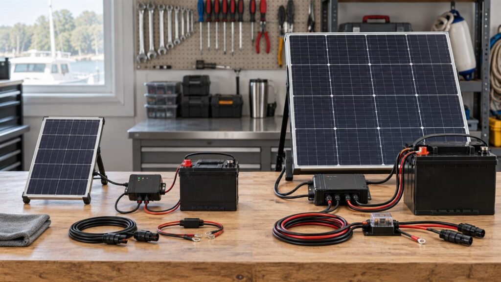
A solar module can meet its electrical target and still fail in the finished product because its mounting method bends the laminate, traps water, shades cells or makes a cable impossible to service. Solar panel mechanical integration therefore starts with the enclosure and its use conditions, not a choice between tape and screws in isolation.
For an OEM product, the right mounting method must hold the module through handling and environmental exposure while allowing the module, enclosure and cable to behave as a system. A frame, adhesive bond and mechanical fasteners can each work. Their risks and validation plans differ.
Define the interfaces before choosing hardware
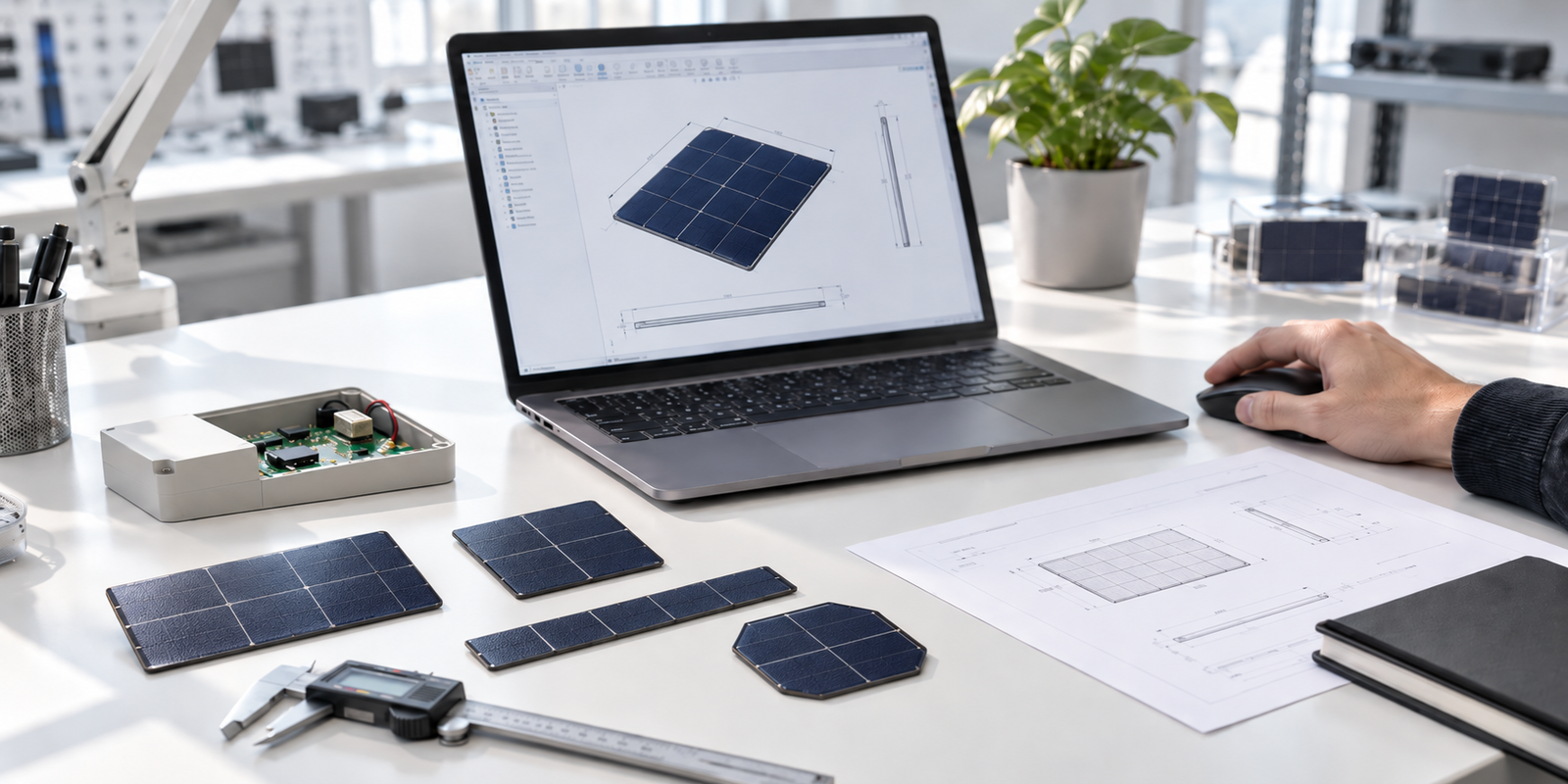
Place the active-cell area, perimeter seal, cable exit, mounting zones and enclosure features on one controlled drawing. Mark the keep-out areas for screw heads, ribs, labels and seals. Confirm the proposed assembly order: can the cable be routed and tested before the module is permanently fixed?
Record the loading case. A stationary sensor housing sees different forces from a portable lid or vehicle-mounted enclosure. Include vibration, impact, cleaning, thermal cycling and the possibility that a user pulls on the cable. If the enclosure itself flexes, confirm how much movement reaches the solar laminate.
The small custom solar panel range supports application-specific dimensions and electrical interfaces. The mechanical drawing must still state the actual support and clearance requirements for the chosen construction.
Compare three attachment approaches
| Approach | Where it helps | Main design question |
|---|---|---|
| Frame or tray | Locates the module and can make replacement easier | Does the frame shade cells, collect water or press on the edge seal? |
| Adhesive or tape | Keeps the visible surface clean and distributes some loads | Are both substrates suitable, prepared and tested across temperature and ageing? |
| Fasteners and brackets | Gives a defined mechanical retention path | Do holes, local stresses and sealing details suit the module construction? |
A hybrid design may use a tray for location and an adhesive for support, or fasteners for a removable cover. Do not assume two weak methods automatically become one strong method; define which element carries each load.
Treat adhesive selection as an engineering decision
An adhesive bond depends on the actual backsheet and enclosure material, surface finish, cleaning process, application pressure and cure or dwell conditions. Differential thermal expansion can put the bond in peel or shear. A generic statement that a tape is “outdoor grade” does not prove compatibility with the proposed surfaces.
The 3M VHB application guidance describes surface preparation, application pressure and material-specific precautions. It is a method reference, not approval of any particular adhesive for a SiborTech module. Ask the adhesive supplier to review the exact joint geometry and test representative production surfaces.
Specify bond width, application location and inspection method on the drawing. Keep adhesive away from an optical or electrical area unless the module design explicitly allows it. Plan a way to identify incomplete contact or contamination during assembly.
Keep fasteners away from unintended stress paths
Do not drill a finished solar laminate simply to match an existing enclosure. Holes, eyelets or bracket interfaces must be designed into a construction that supports them. A screw placed too close to the active area or edge seal can create a local stress concentration or a water path.
If a frame clamps the module, define the compression limit, gasket material and tolerances. Confirm whether the module can expand relative to the housing. Use a representative stack-up, not only nominal CAD dimensions. Check that assembly tools and replacement procedures do not contact the cell surface.
Validate the installed assembly
Test the actual enclosure with the intended module revision. Inspect fit, cell shading, cable strain relief and water paths before environmental testing. Then select vibration, drop, thermal, humidity or cleaning tests from the application risk, with written pass criteria. Recheck electrical output and visible damage after the exposures.
The prototype testing guide covers module-level approval; this integration review adds the enclosure, attachment and assembly process. Record the mounting materials and process revision in the test report. A good result for one adhesive or bracket does not automatically qualify a later substitution.
For a technical review, send the enclosure drawing, installed orientation, material list and expected exposure to SiborTech. Those inputs let the panel and mounting method be assessed together.