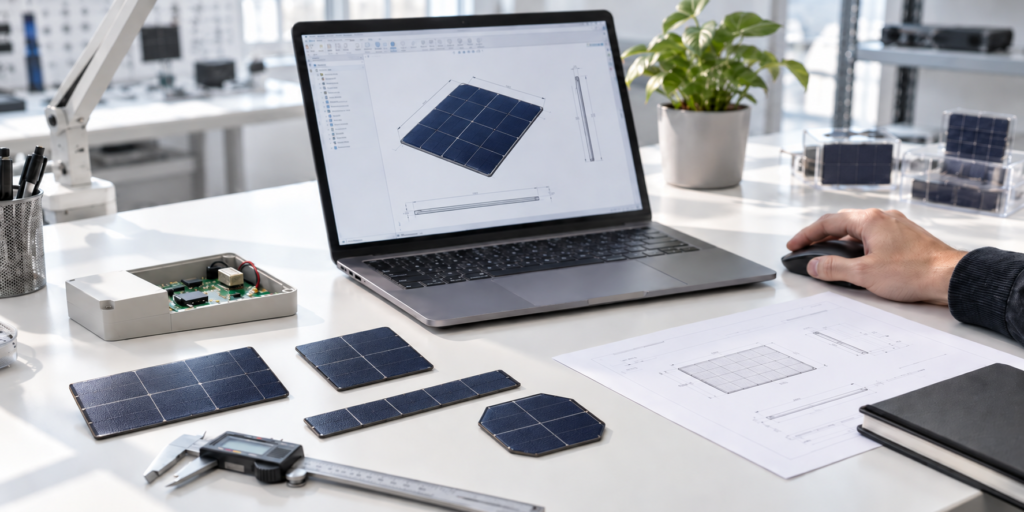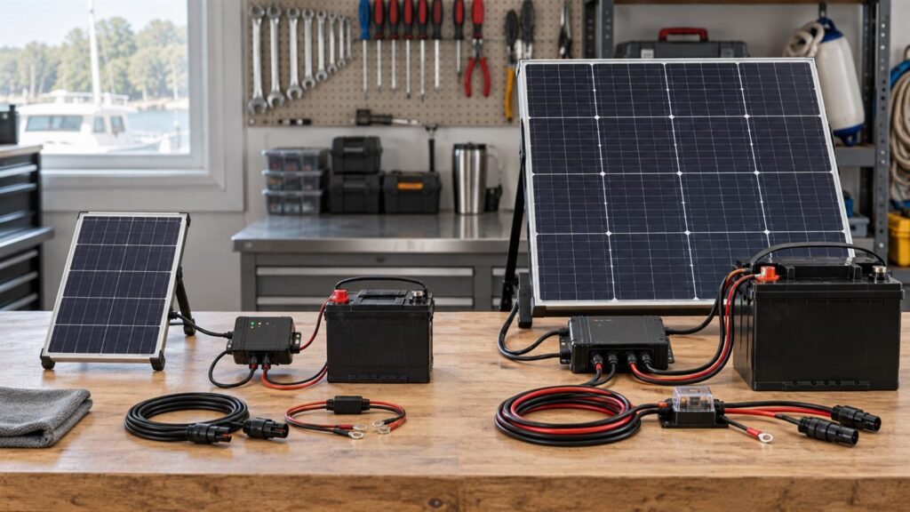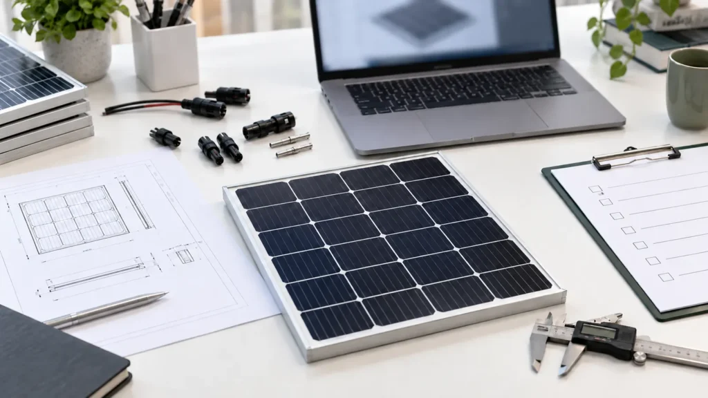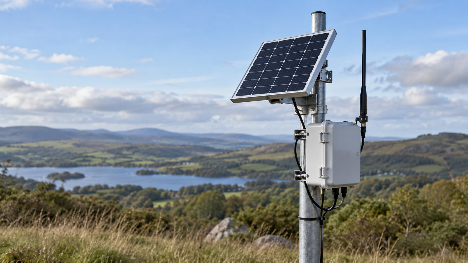
A small sensor may have enough solar-cell area on a drawing yet collect too little energy after it is installed. An enclosure lip can shade the active surface, a gasket can crowd the cable exit, or the service position can turn the panel away from available light. A solar-powered sensor enclosure needs an integration review before its tooling is released.
This article focuses on the mechanical and optical interface. The solar power budget guide addresses energy demand, while the small custom solar panel range describes module options. The enclosure must make the chosen module useful in the actual location.
Map the installed light path
Document mounting height, orientation, nearby structures and likely seasonal shade. Check whether the sensor will be mounted on a pole, wall, fence or moving asset. A module visible on the front of a product photo may sit under an overhang in the real installation.
Mark the active-cell footprint separately from the module outline. Keep bosses, labels, covers, bezels and mounting straps out of the intended light path. A transparent window may introduce reflection, dirt and an extra seal; test it as part of the finished enclosure rather than assuming it has no optical cost.
Make a controlled mechanical interface
The drawing should show module support, edge clearance, cable exit, connector location and strain relief. Decide whether the module is bonded, retained in a tray or captured by a cover. Allow for the actual thickness and tolerances of the module and the enclosure. Avoid forcing a rigid laminate to follow a curved housing unless the construction is approved for that shape.
Any hole or cable pass-through can become a water path. The correct sealing method depends on the enclosure’s exposure and service plan. A laboratory fit check does not establish an IP rating; qualification needs the finished configuration and the relevant test method.
Plan for temperature and maintenance
The panel and electronics may see different temperatures inside the same housing. Review heat from sunlight, a dark enclosure surface, the battery and internal electronics. Also consider condensation, cleaning chemicals and the possibility of an obstructed window. If the module is permanently bonded, define what happens when the cable or panel needs replacement.
The design should permit inspection during assembly: can an operator confirm connector seating, polarity and gasket placement before closing the case? Can a failed module be diagnosed without destroying a sealed product? These details affect both production yield and field service.
Validate with the real device cycle
Build a representative enclosure with the intended module, coating, window and mounting hardware. Measure the PV behavior at the installed orientation and under planned shade cases. Then operate the complete sensor through its normal sleep, measurement and transmission cycle. A bench supply or bare module test cannot reproduce the light path and thermal behavior of the assembly.
Use a small decision table in the prototype report:
| Question | Evidence to record |
|---|---|
| Is the active area unobstructed? | Installed photos and shade observations |
| Is the interface protected? | Cable and seal inspection after assembly and exposure |
| Does the device recover? | Storage and load measurements after low-light operation |
| Can it be serviced? | Demonstrated diagnosis and replacement procedure |
Record the test configuration alongside the results: enclosure revision, module revision, mounting angle, light source, temperature and battery state. Without those details, a later team may attribute a charging shortfall to the panel when the real cause is a changed lip, window material or installation position.
The prototype testing guide explains how to define measurable acceptance criteria. For a sensor enclosure, add the finished device’s operating cycle and installation geometry to that plan.
If you are specifying a sensor housing, send SiborTech the enclosure drawing, intended mounting view and load profile. Those inputs help determine a module geometry and cable route that can be tested in the finished product.