Choosing a solar panel from peak device current usually produces the wrong answer. A battery-powered product may sleep for hours, transmit for seconds, and draw a brief current peak that the panel never supplies directly.
A solar power budget converts those operating states into energy over time. It then accounts for charging losses, useful light, storage autonomy, and design margin. Only after that work should the team decide what panel area and electrical configuration to evaluate.
Power and Energy Are Different
Power is an instantaneous rate, measured in watts. Energy is power accumulated over time, often expressed in watt-hours.
A 2 W load operating for one hour uses 2 Wh. The same load operating for six minutes uses 0.2 Wh. For an intermittent device, the duration of each state matters as much as the current in that state.
This distinction is central to solar design. The panel harvests energy during available light, while the device may consume energy at a different time.
Step 1: List Every Operating State
Create a load table from measurements or component data. Do not use only the average shown by a development board.
Typical states can include:
- Deep sleep
- Sensor warm-up
- Measurement
- Local processing
- Radio receive
- Radio transmit
- Indicator or display activity
- Data storage
- Heater, motor, or actuator operation
- Fault or retry behavior
For each state, record voltage, current, duration, and events per day. If the voltage changes across the system, calculate energy at the relevant rail and account for conversion later.
| State | Voltage | Current | Duration per event | Events per day | Daily energy |
|---|---|---|---|---|---|
| Sleep | Project value | Project value | Project value | Project value | Calculate |
| Measure | Project value | Project value | Project value | Project value | Calculate |
| Transmit | Project value | Project value | Project value | Project value | Calculate |
Use measured values when hardware exists. Data-sheet maximums can be useful for limits, but they may not represent normal energy use.
Step 2: Calculate Daily Load Energy
For a constant state:
Energy (Wh) = Voltage (V) x Current (A) x Time (h)
Calculate each state and add them. Keep the working table visible so a firmware or hardware change can be traced to the total.
Pay attention to small continuous loads. A regulator quiescent current, always-on indicator, battery gauge, or leakage path can consume more daily energy than a brief sensor event.
Also model abnormal but credible behavior. Network retries, weak signal, cold starts, or repeated sensor warm-up can change the result.
Step 3: Add Conversion and Charging Losses
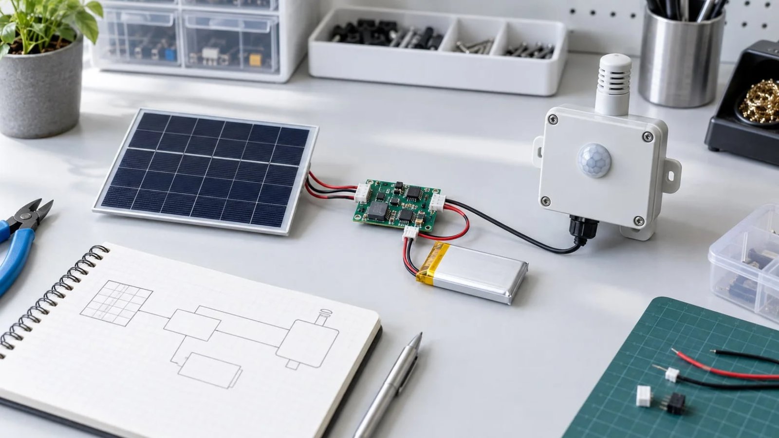
The panel, charger, battery, voltage converters, and wiring do not transfer every harvested watt-hour to the load. Their losses vary with operating point, temperature, battery state, and component choice.
Build the budget from the actual architecture:
- Panel to charge-controller or PMIC input
- Charging conversion
- Battery charge and discharge behavior
- DC/DC or LDO conversion to each load rail
- Cable and connector loss where relevant
- Standby consumption of the power-management circuit
Early in development, a documented engineering allowance is reasonable. Replace it with measurements as the prototype matures.
Step 4: Define the Light Scenario
Solar energy input depends on more than panel wattage. The design needs a stated light scenario.
For outdoor products, consider geographic location and season, orientation, enclosure shading, dirt, storage time, and expected daily exposure.
For indoor products, light source and spectrum matter. Illuminance in lux describes human-visible brightness, not solar irradiance. Two lamps at the same lux can produce different photovoltaic output. Indoor PV work therefore needs defined lamp type, spectrum where available, distance, orientation, and operating schedule.
Avoid converting lux into watts per square meter with a universal factor. The relationship depends on the light spectrum and sensor response.
Step 5: Separate Peak Power From Daily Energy
A radio or actuator may require more instantaneous power than the panel can supply. The battery or capacitor handles that event, while the panel replenishes energy over a longer window.
- Is the storage and power path able to support the peak current without excessive voltage drop?
- Can the panel replace the energy consumed over the design period?
A design can pass one check and fail the other. A large battery does not correct a long-term energy deficit, and a large panel does not automatically solve a poorly supported current pulse.
Step 6: Define No-Light Autonomy
Autonomy is the time the product must continue operating without useful harvested energy. It may cover nights, bad weather, indoor lights being switched off, transport, or temporary shading.
Consider usable storage energy, battery chemistry and limits, temperature, verified aging allowance, reserve for communication, and recovery after a low-energy period.
Battery selection and protection require chemistry-specific design. Follow the cell, pack, and charger supplier requirements rather than using a generic rule.
Step 7: Add Margin With a Reason
Margin should cover identified uncertainty. It should not hide an incomplete model.
Examples include early load estimates, radio connection time, user-controlled orientation, seasonal variation, manufacturing tolerance, and surface contamination.
Document each allowance. As test data improves, update the model instead of accumulating hidden safety factors.
Step 8: Convert the Budget Into Panel Requirements
The energy model gives a required harvested-energy target under defined conditions. The panel design must then fit the available area and work with the charging circuit.
Review active area, operating and open-circuit voltage, expected current, cell arrangement, charger startup, cable loss, orientation, shading, surface, and construction.
For small modules, the voltage target may require a series-cell layout that competes with the available area. This is where electrical and mechanical design must be reviewed together.
SiborTech’s small custom solar panels can be developed around project-specific dimensions, shape, voltage, current, material, and connector requirements.
Step 9: Validate the Complete Energy System
Bench measurements of the load are necessary, but they are not the final test. The prototype should be operated through representative energy cycles.
Measure energy used in important states, charger behavior at low input, battery condition, recovery after no-light periods, startup from depletion, and performance under representative orientation and shading.
Record the light source and test conditions. A result without those conditions cannot be compared or repeated reliably.
Common Power-Budget Mistakes
Using peak current as average current
This can greatly overstate energy use. Model duration and frequency.
Ignoring sleep and standby current
Small continuous loads accumulate for 24 hours per day.
Treating panel nameplate power as daily energy
Nameplate power is measured under defined conditions. It is not a promise of energy in the intended installation.
Sizing the battery and panel independently
Storage, charging, load behavior, and light availability form one system.
Testing under an undefined lamp
For indoor PV, lamp type and spectrum can materially change the result.
FAQ
Should I start with panel wattage or battery capacity?
Start with the device load and operating schedule. Then define light conditions and autonomy before selecting storage and panel requirements.
How do I handle a short radio current peak?
Check the storage device, wiring, and regulator for peak-current delivery. Include the event’s energy in the daily budget, but do not assume the panel supplies the pulse directly.
Can lux be used to size an indoor solar panel?
Lux is useful only with a defined light source and test method. It cannot be converted to photovoltaic input with one universal factor.
How much design margin should I add?
Use margins tied to identified uncertainty and risk. Replace early assumptions with measured values during prototyping.
Next Step
If your project has a defined load profile and limited panel area, discuss the project with SiborTech. Share the load table, battery and charger details, enclosure drawing, and expected light conditions.