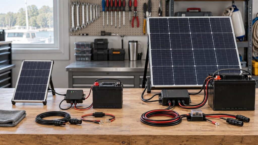
A product enclosure may appear to offer enough room for a solar panel, yet the first layout can still miss its voltage target or leave less active area than expected. The reason is simple: outer dimensions are not the same as usable cell area.
A small solar panel cell layout has to balance electrical configuration, cell geometry, inactive margins, cable routing, appearance, shading, and manufacturing constraints. These decisions should be reviewed together before the enclosure and charging circuit are frozen.
Start With the Electrical Interface
The layout must work with the circuit receiving power from the panel. Useful inputs include the charger’s operating range, maximum input voltage, startup behavior, current limit, battery configuration, and expected light conditions.
Cells connected in series increase module voltage. Parallel paths can increase current. That basic rule is useful, but it does not define a finished layout. The practical result also depends on cell format, interconnection, available area, cutting constraints, and how the product will be shaded.
A voltage target based only on battery nominal voltage can be misleading. The panel must be evaluated with the intended charging architecture and its input limits.
Outer Area Is Not Active Area
The full panel outline cannot normally be filled with active cell material. Space may be required for:
- Edge sealing and encapsulation
- Cell-to-cell spacing
- Interconnects and soldering areas
- Cable exit and strain relief
- Mounting holes or adhesive zones
- Corner radii and enclosure keep-outs
- Cosmetic borders and alignment tolerance
- Manufacturing and cutting tolerance
These features reduce active area, but they are not wasted by default. They may be necessary for a repeatable module that fits and connects correctly.
An enclosure drawing should identify the maximum outline and every keep-out zone. A simple length-by-width value is not enough when a camera, antenna, screw boss, display window, or cable channel occupies part of the surface.
Cell Size and Geometry Change the Options
Available cell formats influence how efficiently a shape can be filled. A layout based on large rectangular pieces may use a simple enclosure well but fit poorly around a notch or narrow section. Smaller pieces can offer more layout freedom, but they may add interconnections, handling, or production complexity.
The best arrangement is not automatically the one with the highest apparent fill. The layout also needs stable electrical connections, practical spacing, acceptable appearance, and a manufacturing process suitable for the project.
For a custom-size monocrystalline solar panel, provide the drawing before committing to voltage and current targets. The usable geometry may change what is feasible. The published custom monocrystalline solar panel design guide provides the broader technology context; this article stays focused on the internal cell map.
Irregular Shapes Require an Early Trade-Off
Custom shapes can help a solar module follow a product enclosure, but the outline may divide the available surface into areas that are difficult to use electrically.
Consider a panel with a deep notch. The remaining area may be large enough in total, but not arranged in a way that supports the required number of equal cell sections. Forcing the electrical target into that outline can create narrow cell pieces, extra interconnects, visible imbalance, or unused pockets.
It may be better to adjust the enclosure boundary, move a mounting feature, change the cable exit, or review the charging voltage. A small mechanical change can sometimes create a much cleaner electrical layout.
Layout Influences Shading Behavior
Small product-integrated panels are often shaded by the product itself. An enclosure lip, antenna, strap, handle, sensor window, label, or nearby structure can cast a repeatable shadow.
Shading one part of a series path can limit current through that path. Uniformly reducing light across the panel is not the same as covering one cell section. The effect depends on the circuit arrangement and the shape and position of the shadow.
Before approving the layout:
- Mark expected shadow zones on the product drawing.
- Review their relationship to cell sections and interconnects.
- Test representative shadow patterns with the intended charger and load.
- Record light conditions so results can be compared.
Do not assume that a layout that performs well under a uniform lamp will behave the same way when one corner is covered.
Appearance Can Be an Engineering Requirement
For visible consumer or commercial equipment, cell alignment, color consistency, border width, and symmetry may matter. These requirements should be stated rather than judged only after the prototype arrives.
Cosmetic priorities can compete with active area. A centered and symmetrical layout may use less of an irregular outline than a layout optimized only for output. Neither choice is universally correct. The product team should decide which characteristics are required and which are preferred.
Reference images, controlled drawings, and an approved sample make cosmetic acceptance more consistent.
Cable Exit and Mounting Affect the Layout
The cable should not be added after the active pattern is complete. Its exit position, termination area, bend direction, strain relief, and enclosure route all need space.
Mounting features can have the same effect. A hole near the edge may interrupt a cell row or leave too little sealing margin. Adhesive zones may need a stable backing area. Mechanical fasteners need clearance from cells, conductors, and cable routing.
Review the panel, cable, and mounting concept as one assembly.
Design for Manufacturing, Not Only the Drawing
A layout can be electrically plausible and still be difficult to produce consistently. A manufacturability review may consider cell handling, cut pattern, interconnect access, alignment tolerance, lamination, edge construction, cable attachment, inspection, and test points.
Extremely narrow features or tight tolerances can reduce process margin. Extra cell pieces and interconnects may add work and inspection points. The supplier should identify these risks before the prototype drawing is approved.
No universal fill factor or efficiency assumption should be used to judge every custom module. Performance depends on the selected cells, layout, construction, area definition, and test conditions.
Layout Review Checklist
| Area | Question to confirm |
|---|---|
| Enclosure | Is the controlled outline and every keep-out zone defined? |
| Electrical | Does the layout match the charger input range and current need? |
| Active area | Have margins, spacing, interconnects, and cable areas been deducted? |
| Shading | Are repeatable product shadows mapped onto the layout? |
| Appearance | Are symmetry, border, color, and alignment requirements documented? |
| Cable | Is the exit, termination, bend, and strain relief included? |
| Mounting | Do holes, adhesive, frames, or fasteners have adequate clearance? |
| Production | Can the cell pieces and interconnects be made and inspected consistently? |
| Validation | Are loaded electrical tests and representative shading tests planned? |
Common Layout Mistakes
Treating the bounding rectangle as usable cell area
Keep-outs, sealing, spacing, and interfaces reduce the active region.
Fixing the enclosure before checking the electrical layout
A small change to a notch or mounting feature may improve cell use substantially.
Choosing voltage without sharing the charger limits
The module and charging circuit must be reviewed as one electrical interface.
Ignoring predictable shadows
A strap or enclosure feature can affect one cell section every day.
Approving only a visual rendering
The prototype must be tested under defined light with the intended electronics.
FAQ
Can any outer shape be filled with solar cells?
Not necessarily. Feasibility depends on available cell formats, electrical configuration, inactive margins, interconnections, and production constraints.
Does adding more series cells always improve a small panel?
More series-connected cells raise voltage, but the result must remain compatible with the available area and charging circuit. Current and shading behavior also need review.
Why are equal-size cell sections often preferred?
Equal sections can support a more consistent series path and cleaner appearance, but the appropriate layout depends on the module design and cell process.
When should the layout be tested for shading?
Test during prototyping, using the real enclosure or a representative mock-up and the intended charging electronics.
Next Step
If your product has a fixed solar surface, send us the enclosure drawing, keep-out zones, charger input limits, cable location, and expected shading. The team can review a small custom solar panel layout before the mechanical design is frozen. Share the available area and electrical interface for an initial layout review.