Adding a USB-C connector does not automatically make a portable solar charger compatible with modern devices. The product must behave as a controlled USB power source while its solar input changes continuously. For an OEM buyer, the key specification is the complete chain: panel, regulator, optional storage, USB Power Delivery controller, connector, cable and protection.
This guide explains what to define for a USB-C solar charger OEM project. It focuses on output architecture and verification, while our OEM foldable solar charger development guide covers the broader product-development process.
Start with the target device and use case
List the actual devices to be powered: phone, tablet, camera, radio, power bank or laptop. Record their supported input profiles and whether charging must continue in weak or intermittent sun. USB-C output is too vague because USB-C describes a connector and interface family, not one guaranteed power level.
Separate the product class as well:
- Hiking solar chargers, approximately 15–40W: optimized for low mass and direct charging of small electronics or power banks.
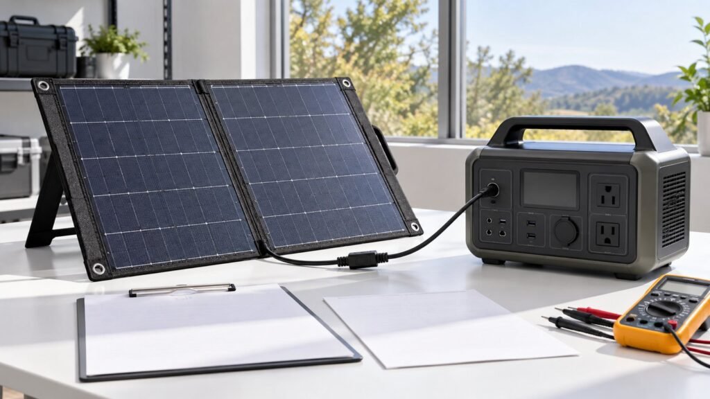
- Camping foldable solar panels, approximately 60–400W: intended mainly for larger battery systems or portable power stations, often using DC connectors; USB-C may be an additional regulated output rather than the main interface.
Do not merge those categories into one nominal range. Their output electronics, cable systems, thermal conditions and buyer expectations differ.
Define the USB power behaviour
At minimum, specify the output voltage, maximum current and number of ports. If USB Power Delivery is required, define the source profiles that the product will advertise. The connected device requests a supported power contract; the charger must not advertise a profile it cannot maintain.
| Requirement | OEM decision |
|---|---|
| Interface | USB-C without PD, USB PD, or USB PD with programmable supply features |
| Profiles | Exact voltage/current combinations supported |
| Power limit | Per port and total shared capacity |
| Low-sun response | Derate, disconnect, renegotiate or buffer from storage |
| Restart behaviour | How the port recovers after input collapse |
| Cable | Length, current rating, captive or detachable, environmental grade |
Higher advertised USB PD capability does not create more solar power. A 20W panel cannot reliably support a high power contract when heat, off-angle light and conversion losses are considered. Advertised profiles need headroom or an energy buffer.
Choose direct solar output or buffered output
Direct regulated output
The panel feeds a DC-DC stage and USB controller directly. This can reduce weight and cost, but clouds and movement can cause the available power to change faster than the connected device expects. The design needs graceful current limiting, voltage stability and recovery logic.
Battery-buffered output
An internal battery or supercapacitor separates the USB output from short solar fluctuations. It can improve charging continuity, but adds battery management, thermal considerations, transport rules, ageing and safety requirements. Define whether the battery is merely a small buffer or a user-facing power bank.
Panel intended to charge an external power bank
Many hiking systems use a separate storage device. In that case, test interoperability with representative power banks and verify that repeated cloud interruptions do not leave the input latched off. The external device still controls how much power it accepts.
Match the panel operating range to the converter
The solar array’s Vmp and Voc must remain within the input limits of the regulator across temperature and light conditions. The converter must also start correctly when irradiance rises and avoid dragging the panel voltage down when the requested load is too high.
Specify the number and arrangement of solar sections, nominal power, expected operating voltage and connector losses. Folding hinges and long cable runs add resistance. A theoretical panel rating should not be used as the guaranteed USB output rating.
Plan low-light behaviour deliberately
Portable solar chargers regularly experience moving shade, passing clouds and changing orientation. Decide what the user should observe when solar input becomes insufficient:
- maintain a lower-power contract if supported;
- limit current while holding a stable voltage;
- disconnect cleanly and retry after a defined delay;
- use stored energy for a controlled ride-through period;
- indicate insufficient solar input without consuming excessive power.
Uncontrolled cycling can cause a phone or power bank to repeatedly start and stop charging. Recovery behaviour should be tested, not inferred from steady-state bench measurements.
Specify the connector and cable as outdoor components
The USB-C receptacle is often the most exposed part of the system. Define its location, cover, ingress strategy, insertion life and protection from side loads. A captive cable removes one user connection but creates a strain-relief and replacement question. A detachable cable improves serviceability but relies on the user choosing a suitable cable.
For higher-current profiles, cable capability matters. USB Power Delivery communication and current rating must be compatible with the intended profile. If the product is marketed using USB-IF trademarks or certification claims, the applicable compliance and licensing path should be planned separately; do not assume component-level claims automatically apply to the finished charger.
Add electrical protection and thermal management
The output board normally needs protection appropriate to its topology, such as overcurrent, short-circuit, input overvoltage, output overvoltage, reverse-current and electrostatic-discharge protection. Component temperatures should be reviewed under strong sun, high ambient temperature and maximum output.
The electronics enclosure may sit behind a dark panel and become hotter than the surrounding air. Conversion efficiency affects both usable power and temperature, so test the complete folded product rather than only the controller board on an open bench.
Keep the folding structure and electronics serviceable
Decide where the junction housing, controller and output ports are mounted. They should not create a hard point that damages cells when folded. Cable routes should avoid hinge pinch zones, and the folded package should protect connectors during transport.
For a lightweight use case, see the dedicated foldable solar charger for hiking. For larger systems designed around stored energy, review camping foldable solar panels.
Define a verification plan
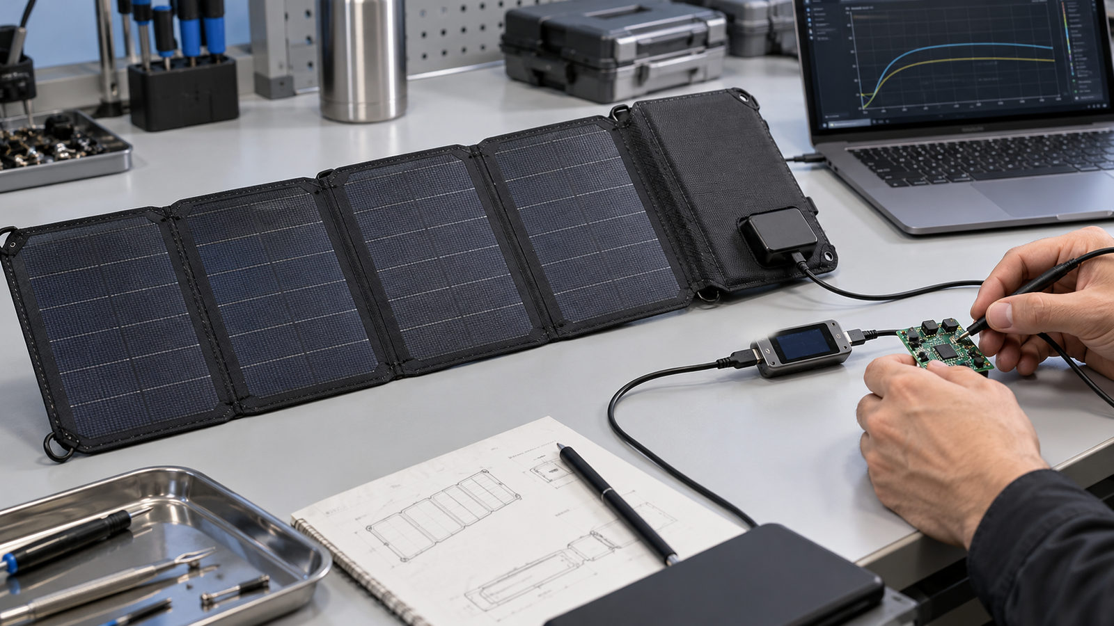
An OEM acceptance plan should include supported USB-C and USB PD profiles with representative devices, output voltage and current under steady input, cloud and shading transitions, startup and automatic restart, short-circuit and overload response, connector temperature, multiport power sharing, folding, cable strain and environmental checks.
Record the test conditions. Solar output depends on irradiance, panel temperature and orientation, so a power claim without conditions is not a useful engineering acceptance criterion.
What to include in an OEM specification
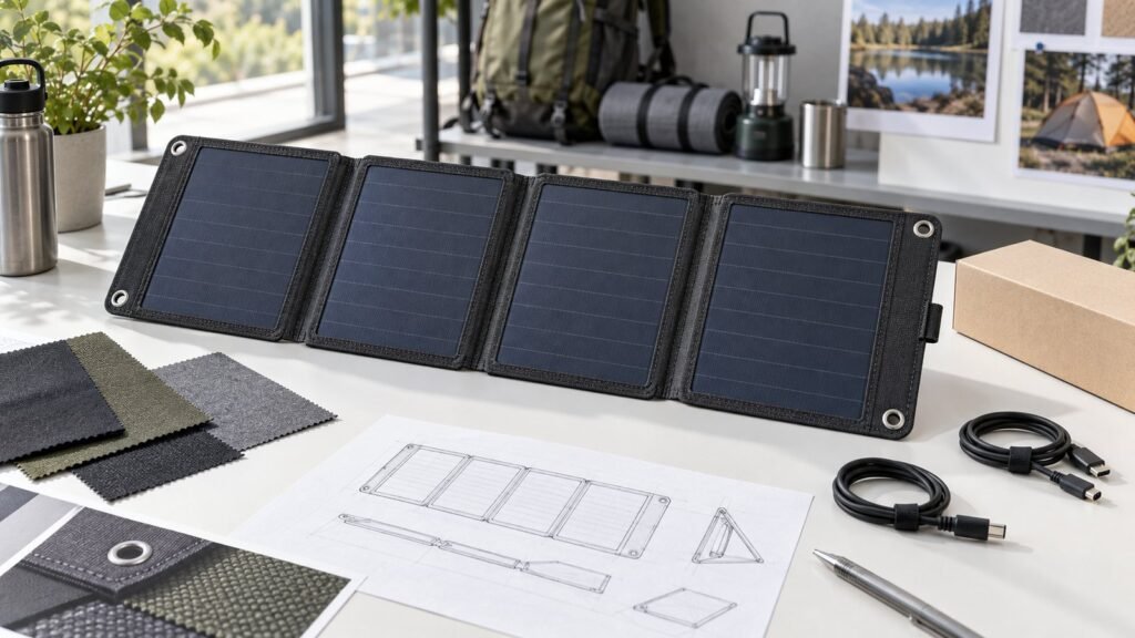
Provide the target application, panel power class, unfolded and folded dimensions, weight target, lamination material, number of folds, port count, USB profiles, cables, connector covers, controller location, environmental limits and packaging needs. State whether the charger connects directly to electronics, an external power bank or a portable power station.
If you are defining a USB-C portable solar product, send us the output profile and mechanical requirements so the panel and electronics can be reviewed together.