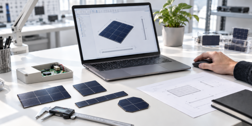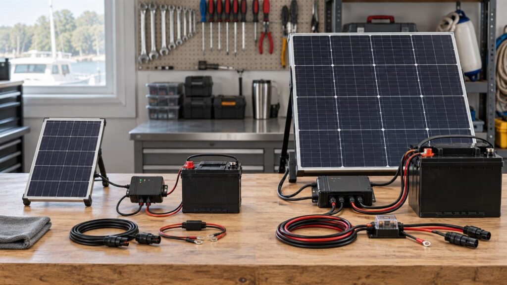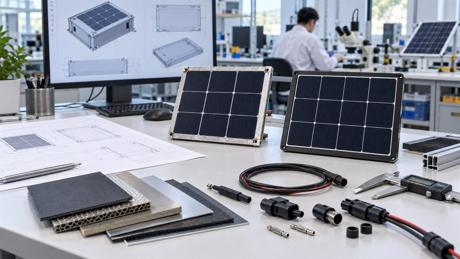
To choose a small custom solar panel for embedded electronics, start with the constraints of the finished device. The panel must share space with an enclosure, charging electronics, storage and the product’s daily workload. A module that fits the opening can still be electrically or mechanically unsuitable.
We treat selection as a sequence of interface decisions. Calculate the device’s energy requirement first, then compare module constructions against the available space and operating environment. This guide focuses on selection; our IoT solar-panel sizing guide covers the broader energy-sizing workflow.
Define usable photovoltaic area
Overall product dimensions are not the same as active panel area. Leave room for enclosure walls, mounting borders, sealing, holes, electrical contacts and cable clearance. A printed logo or decorative cover may also affect where useful light reaches the module.
Provide a drawing of the complete installation envelope, including the back of the module. Show the intended viewing surface, surrounding obstructions and any recess. This prevents a quotation based on an area that disappears during enclosure design.
Match the module to the charger input
Specify the charging circuit’s permitted input range, startup requirements and operating behaviour, together with battery or storage details. Panel voltage, current and power should be considered under the intended illumination and temperature conditions.
A matching nominal voltage is not enough to establish compatibility. Ask for the proposed electrical configuration and test the sample with the intended electronics. Avoid selecting the panel independently and expecting firmware to resolve an unsuitable hardware interface later.
Choose construction from the environment
Compare front surface, encapsulation, backing, edge treatment and cable termination as a complete module. A material label such as glass, ETFE or PET does not describe the entire product. The same surface material can be used in assemblies with different support and environmental limits.
Describe sunlight, artificial light, temperature, humidity, cleaning, chemicals and handling as applicable. Do not request a generic “outdoor” construction without explaining the installation. Where a rating or certification is needed, identify the relevant finished assembly and evidence rather than inferring it from a component.
Resolve the mechanical interface early
Choose whether the module will be bonded, clipped, framed or retained in a recess. Record support, clearances, dimensional tolerances and the replacement method. For a curved installation, ask for the permitted geometry and whether movement is allowed after assembly.
Review cable exit direction with the enclosure drawing. A lead that looks convenient in isolation may collide with a battery, fastener or sealing feature. Confirm connector mating space and strain relief before the electronics and housing are released.
Compare candidate modules on an equal basis
Use the same available area, illumination, loading method and measurement conditions when comparing prototypes. Differences in test conditions can look like technology differences. Record active area and complete external dimensions separately.
Ask whether quoted output comes from a cell, a module sample or the exact proposed construction. A research result or another customer’s sample is useful background, but it is not acceptance evidence for your device.
Use a selection matrix
| Constraint | Question for each candidate |
|---|---|
| Space | Does the entire module and termination fit? |
| Electrical input | Does it operate with the chosen charging circuit? |
| Light exposure | Has output been assessed in the intended position? |
| Construction | Are support, sealing and handling appropriate? |
| Assembly | Can it be installed consistently without local stress? |
| Production | Are tolerances, acceptance criteria and substitutions defined? |
Approve a prototype around the product
The selection process ends with a trial of the assembled device, not just a dimensional drawing. Check charging startup, operating cycles, shaded periods, enclosure fit and installation handling. Record deviations and decide which risks need further validation.
Keep a controlled specification for the approved module. If a material, cell layout, connector or cable changes, review whether the earlier evidence still applies. A repeat order should refer to the approved revision rather than a photograph alone.
See our small custom solar panel options and custom development process. Send the enclosure envelope, charger requirements and use conditions for a focused selection review with us.