Partial shading of a small solar panel should be evaluated from the actual shadow pattern and electrical layout. Covering a small part of the surface does not necessarily cause a proportional reduction in useful power. A strap, enclosure edge or antenna can affect the module differently from a uniform change in illumination.
We use shading tests to connect module design with the product’s real installation. The aim is to identify better placement and a suitable electrical interface, rather than predict every shadow from panel area alone.
Partial shade and uniform dimming are different tests
Uniformly reducing illumination affects the module across its surface. A local shadow may affect only some cells or sections. In a series-connected path, a current-limiting section can influence the behaviour of the wider circuit. The precise result depends on cell layout, interconnections, bypass arrangements and the connected electronics.
Do not assume every compact module includes bypass diodes or that it behaves like a larger rooftop module. Request the relevant design information for the sample being tested. Victron’s explanation of shading effects illustrates how shade and bypass paths can change a module’s output. Confirm the actual construction of a compact module rather than assuming the same bypass arrangement.
Find shadows created by the product
Start with features close to the panel: enclosure walls, recessed openings, handles, mounting brackets, cables and labels. For portable products, include straps and the way users attach or hold the panel. For fixed equipment, inspect surrounding structures and likely installation mistakes.
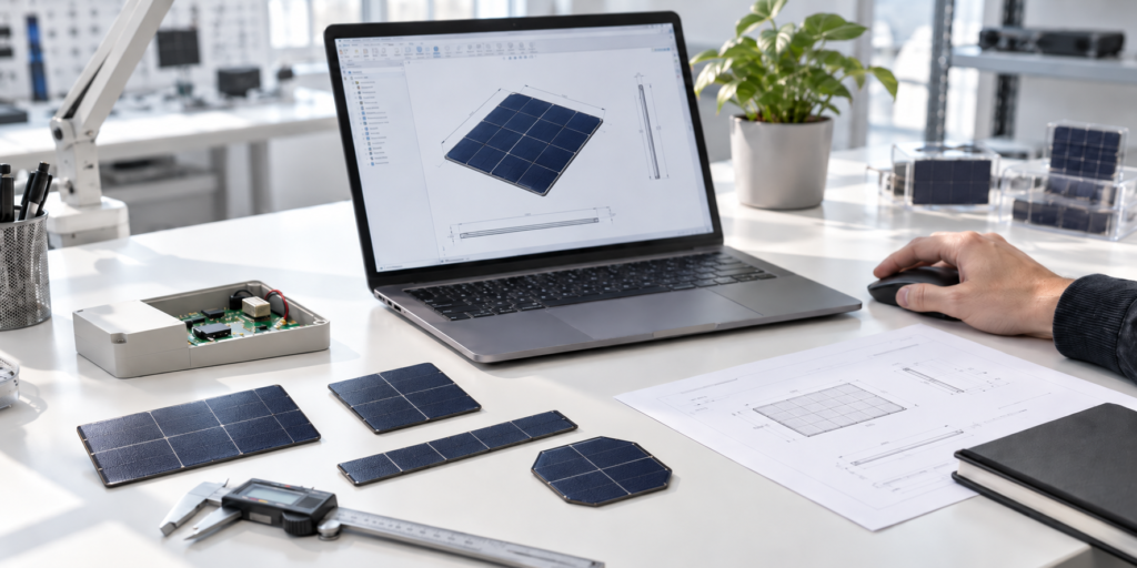
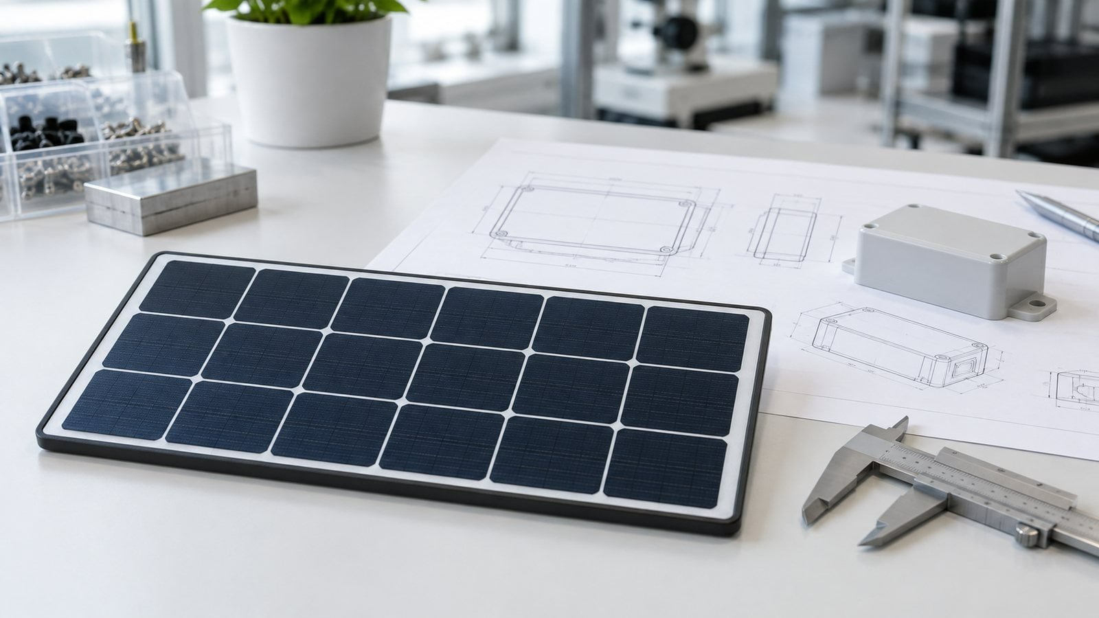
A useful drawing shows the panel’s active area and the objects that can obstruct light. Photographs taken at several likely deployment angles can reveal a problem that a front-on product rendering misses.
Test the patterns that matter
Use repeatable masks or controlled obstructions to reproduce relevant shadows. Record the mask shape, position, panel orientation, light source and electrical load. Move the obstruction across the areas that the actual product can shade.
Keep a uniformly dimmed comparison separate from a locally shaded comparison. If conditions change while testing outdoors, record that uncertainty rather than assigning every output change to the shadow.
Measure useful operation with the real electronics
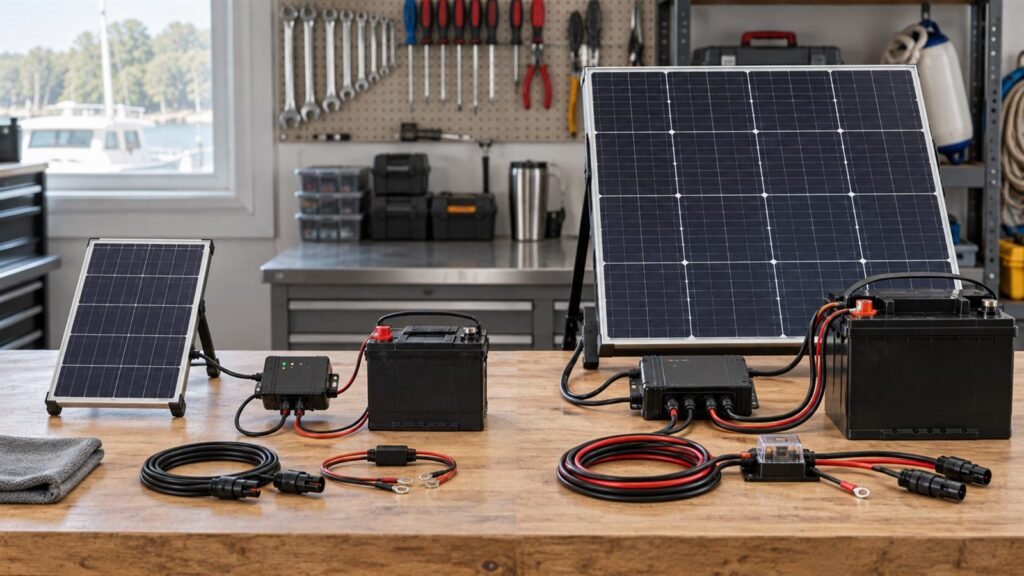
Open-circuit voltage alone cannot show how well the product charges under shade. Test the module with an appropriate load and, when possible, the intended power-management circuit, storage and device.
Observe startup, charging behaviour, interruption and recovery. A controller may respond differently to changing input from another controller, so a result with one bench setup does not automatically approve every charging circuit.
Record an actionable result
| Record | Purpose |
|---|---|
| Panel revision and cell layout | Ties the result to the actual design |
| Shadow shape and location | Makes the test repeatable |
| Illumination and temperature conditions | Explains the measurement environment |
| Load or charging circuit | Defines the electrical operating point |
| Output and recovery behaviour | Shows the consequence for the device |
Consider placement before adding area
Moving the module, reducing a recess or rerouting a strap may improve exposure without changing nominal power. A cell-layout change may also be worth investigating, but it must be assessed against voltage requirements, usable area, appearance and production constraints.
Compare proposed changes under the same test conditions. Do not describe a layout as shade-proof. A change that helps with one obstruction may have little benefit for a different shadow pattern.
Include shade in the product’s energy assessment
A brief shaded event and a daily obstruction have different consequences. Record how often each pattern occurs and whether the device can defer nonessential work or use stored energy. The final assessment should connect charging input with the required operating schedule.
For safety and repeatability, agree the test procedure with the module and electronics teams. Avoid improvised prolonged stress tests or assumptions about permitted cell temperatures.
Read our guide to small-panel cell layout and IoT solar-panel sizing workflow. Send a drawing or photograph of the likely obstruction so we can review it alongside your custom module requirements.