A PET-laminated solar panel can look suitable during a short bench test and still be the wrong construction for long-term outdoor use. The electrical design may be correct, yet the exposed polymer surface can gradually lose optical clarity, adhesion, or mechanical strength as sunlight, heat, moisture, and movement act together.
That does not make every PET panel unsuitable. It means the buyer must define where the panel will be installed, how long it must remain exposed, and what protection the finished product provides. The right question is not simply “Is PET good or bad?” It is “Is this laminate stack appropriate for the product’s real environment?”
What “PET solar panel” actually describes
PET is polyethylene terephthalate, a polymer used in many films and laminates. In a small solar module, PET may appear in a front layer, a rear layer, or another part of a multilayer construction. Those positions are not interchangeable.
Two panels described as PET panels may use different film grades, coatings, adhesives, encapsulants, thicknesses, edge seals, and manufacturing processes. A film protected inside a product also experiences a very different environment from a film continuously exposed as the outer weather surface.
For this reason, material names alone do not prove outdoor life. Product teams should ask for the complete layer structure and identify which layer is directly exposed.
Why outdoor exposure changes PET
Outdoor ageing rarely comes from one stress acting alone. Sunlight heats the laminate while ultraviolet radiation reaches the polymer. Night-time cooling creates repeated temperature changes. Rain, humidity, condensation, dirt, cleaning, and mechanical bending add further stress.
The combined effect can be more severe than any single laboratory condition. A useful durability review therefore considers the main degradation mechanisms together.
UV-driven chemical change
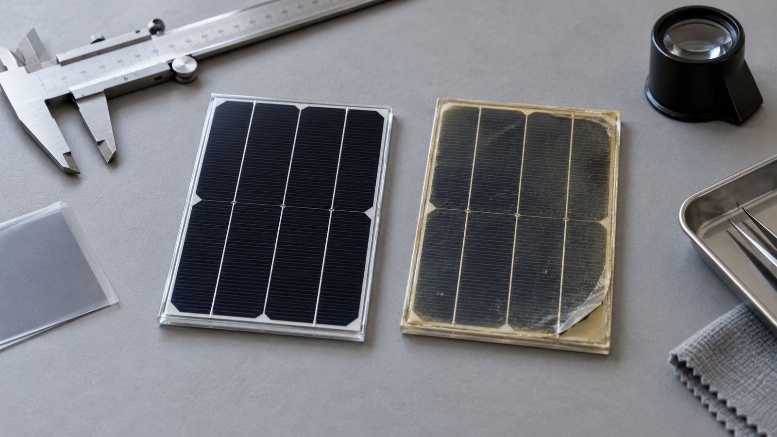
Ultraviolet radiation can break or rearrange chemical bonds in a polymer. Over time, this photo-oxidation may change colour, reduce ductility, or make a surface more brittle. The rate depends on the PET formulation, stabilisers, coatings, total UV dose, temperature, oxygen, and whether another layer filters the radiation.
Visible yellowing is important because it may indicate that the optical path has changed. However, a clear-looking film is not automatically healthy, and a colour change alone does not quantify remaining strength. Visual inspection should be combined with electrical, optical, adhesion, and mechanical checks.
Haze and reduced light transmission
The module depends on light reaching the solar cells. Surface weathering, microcracking, chemical change, contamination, or separation between layers can increase haze or reduce transmission. That can lower the useful light available to the cells even when the cells themselves remain intact.
The effect is especially relevant for a small panel with little excess area. A compact device often has a narrow energy margin, so a modest optical loss can affect charging reliability during weak-light periods.
Embrittlement and cracking
A polymer film that loses flexibility can become more vulnerable to handling stress, product vibration, thermal expansion, or bending. Fine cracks may begin at a stressed edge, an opening, a folded area, or a point where the laminate is forced against a housing.
Cracking is not only a cosmetic issue. Once a protective layer is disrupted, moisture and contamination can reach deeper parts of the laminate more easily.
Adhesion loss and delamination
A solar laminate is a system of interfaces. The front layer, encapsulant, cells, conductor, substrate, and rear layer must remain bonded despite different thermal expansion rates and repeated environmental cycling.
UV exposure, heat, humidity, contamination during production, inadequate surface treatment, or a poorly selected adhesive can weaken an interface. Delamination may begin as a small bubble or lifted edge and then spread. It can change optical transmission, create a moisture path, and concentrate mechanical stress.
Moisture entry at edges and cable exits
The flat centre of a panel is not always the most vulnerable area. Moisture frequently finds a path at cut edges, corners, cable exits, junction areas, mounting holes, or damaged seals.
A product enclosure can make this better or worse. A recessed panel with controlled drainage and a protected cable exit may see less direct water. A panel bonded into a pocket that traps water may stay wet long after rain stops. The mounting design therefore belongs in the durability discussion.
Heat and thermal cycling
Solar modules can become hotter than the surrounding air, particularly when bonded to a dark or poorly ventilated enclosure. Heat can accelerate chemical reactions and place more stress on adhesive interfaces.
Repeated heating and cooling also makes different materials expand and contract by different amounts. Over many cycles, that movement can load cell interconnects, edges, coatings, and adhesive layers. The panel should be tested as part of the finished assembly, not only as a loose sample on a laboratory table.
PET versus ETFE for an exposed front surface
ETFE is often considered for outdoor-facing lightweight modules because it can offer strong weathering and UV-resistance characteristics in an appropriate construction. PET is frequently attractive where cost, flatness, printability, or protected indoor use matters.
This is not a rule that ETFE is always the correct answer. An ETFE-faced panel can still fail if the encapsulant, edge seal, cable exit, or lamination process is unsuitable. Likewise, a well-designed PET-containing laminate may be appropriate when PET is not the unprotected outer weather surface or when the product has a controlled service environment.
For a broader comparison of surface characteristics and construction choices, see ETFE vs PET solar panels. The present article focuses specifically on why an outdoor-exposed PET construction needs a more careful durability review.
When PET may still be a practical choice
PET can remain a sensible engineering choice when the product’s exposure is limited or controlled. Examples may include:
- indoor products powered by strong artificial light;
- panels installed behind a UV-stable transparent window;
- equipment used mainly indoors and moved outside only briefly;
- short-life or replaceable accessories with clearly defined conditions;
- prototypes used to validate electrical and mechanical integration before the final outdoor material is selected;
- rear or internal laminate layers that are not directly exposed.
These examples are not automatic approvals. A cover window may introduce reflection, heat, condensation, or spectral loss. A “temporary outdoor” product may remain outside much longer than expected. The use case must still be tested.
Questions to answer before selecting the laminate
The material decision becomes clearer when the product team documents the actual environment.
| Design question | Why it matters |
|---|---|
| Is the panel directly exposed or behind a cover? | Determines the UV, water, abrasion, and cleaning load on the surface. |
| What is the expected outdoor exposure pattern? | Continuous exposure differs from occasional or seasonal use. |
| Can water collect around the panel? | Standing water and trapped moisture increase risk at edges and exits. |
| What temperatures can the assembled product reach? | Enclosure colour, ventilation, and mounting can raise cell and laminate temperature. |
| Will the product bend, vibrate, or receive impact? | Mechanical strain can accelerate cracking or adhesion loss. |
| Is the panel replaceable? | A serviceable accessory has a different risk profile from a sealed product. |
| What performance margin exists? | A design with little energy surplus is less tolerant of optical or electrical loss. |
Specify more than the surface material
An RFQ that says only “PET solar panel” or “ETFE solar panel” leaves major design decisions undefined. A better specification includes:
- whether PET is the exposed front layer, a rear layer, or an internal layer;
- the required panel outline, active area, thickness, and flatness;
- target Vmp, Imp, Voc, and Isc with the intended charger;
- expected temperature, UV exposure, humidity, water contact, and cleaning;
- minimum bend radius or a statement that the panel must remain rigid;
- edge-sealing method and allowed border width;
- cable-exit position, strain relief, connector, and polarity;
- mounting adhesive or mechanical attachment method;
- appearance limits for haze, colour change, bubbles, and edge lift;
- prototype and validation plan.
These details allow a supplier to review material selection together with cell layout and mechanical integration. Our small custom solar panels are developed around the available product area, electrical target, and construction requirements rather than a material label alone.
Build a realistic validation plan
There is no single accelerated test that proves every outdoor application. A useful programme combines material-level and product-level checks based on the expected risks.
- Record initial appearance, dimensions, electrical output, and adhesion condition.
- Expose representative samples to the relevant UV, temperature, and humidity stresses.
- Include thermal cycling when the assembly will see strong day-night or seasonal changes.
- Test water exposure, drainage, edges, and cable exits in the intended orientation.
- Add bending, vibration, abrasion, or cleaning tests when the use case requires them.
- Recheck optical appearance, electrical behaviour, adhesion, cracking, and corrosion after each stage.
- Test the panel inside the real enclosure with the actual charger and battery.
Acceptance criteria should be agreed before testing. “No visible damage” is usually too vague by itself. Define what amount of colour change, edge lift, output change, or dimensional movement is acceptable for the product.
Make the decision at product level
Outdoor durability depends on the complete laminate and the way the panel is integrated. An exposed PET surface may degrade through UV-driven chemical change, haze, embrittlement, adhesion loss, and moisture-assisted damage. Heat, thermal cycling, bending, and weak edge details can accelerate those processes.
PET may still be appropriate for protected or controlled applications, but the exposure assumptions should be written down and verified. For continuously exposed products, compare alternative front materials, edge designs, and mounting approaches before locking the enclosure.
Review the custom solar panel development process and our application examples when preparing the mechanical and environmental requirements. To discuss a laminate stack, installation area, and validation plan for a specific product, contact our engineering team.