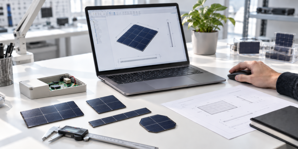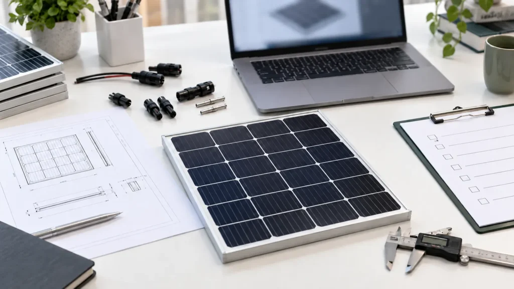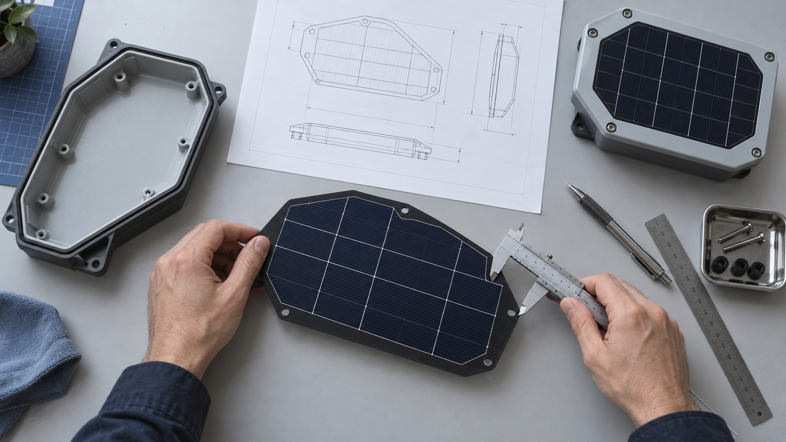
A product enclosure rarely offers a perfect rectangle for solar collection. Screws, seals, display windows, antennas, curves and industrial-design features all reduce the surface that can actually hold active cells. For an OEM team, the right question is not simply “What panel size fits?” It is “What cell layout can deliver useful power inside the safe, manufacturable area?”
This guide explains how to translate an enclosure drawing into a realistic custom shaped solar panel specification. It focuses on geometry, electrical layout and mechanical integration rather than repeating the general panel-sizing process covered in our custom-size monocrystalline solar panel guide.
Start with the usable solar area, not the outer outline
The outside dimensions of a product are not the active solar area. Create a keep-out map before choosing cells. Mark every feature that solar laminate cannot cover:
- fasteners, bosses and service openings;
- gaskets, weld lines and adhesive channels;
- display, antenna or sensor windows;
- curved edges and surfaces with changing radius;
- cable exits and strain-relief zones;
- areas regularly shaded by handles, hinges or accessories.
Then add the inactive border required by the selected construction. Cell edges, interconnects and laminate seals need space. A drawing that shows only the final visible outline can therefore overstate the area available for power generation.
Why shape changes the electrical design
Crystalline cells are electrically connected in strings. Cells in series carry the same current, so a narrow or shaded cell can limit the string. An irregular outline may require different cell fractions, multiple rows or a stepped layout. That is not only a visual arrangement; it changes voltage, current, interconnection length and mismatch risk.
For example, a wide lower section and a narrow upper section may appear to use the enclosure efficiently. But if the narrow section forces very small cell pieces into the same series string, the usable current may be governed by those pieces. Sometimes a simpler layout with slightly less active coverage produces a more predictable module.
Review the effect of cell layout on a small custom solar panel before fixing the mechanical shape.
Choose a practical shape strategy
1. Rectangular active area inside a shaped border
This is often the lowest-risk option. The laminate or substrate follows the product outline while the active cell field remains rectangular. It simplifies cell cutting and string design, but leaves more inactive area.
2. Stepped cell layout
Rows with different lengths can follow a tapered enclosure. The design must still keep compatible cell areas within each electrical path. Interconnect routing and insulation around the steps need review.
3. Multiple electrical sections
Two separate sections may use disconnected areas around a display or mechanical feature. Combining them requires an intentional series or parallel architecture and careful analysis of unequal illumination. Do not assume two differently oriented areas will behave like one uniform panel.
4. Separate modules instead of one complex module
Two conventional modules can be preferable when the enclosure has a hinge, a strong curvature change or permanent shading between surfaces. This adds wiring and sealing work, but may simplify service and production.
Mechanical integration questions to resolve
| Design input | Why it matters | What to provide |
|---|---|---|
| Enclosure material | Affects adhesive choice, thermal movement and surface preparation | Material grade and surface finish |
| Mounting method | Controls border width and load transfer | Adhesive, screws, frame or insert details |
| Flatness and curvature | Rigid laminates cannot conform to every surface | 3D model, radius and flatness tolerance |
| Ingress protection concept | Cable exits and edges can become leakage paths | Seal stack-up and cable-entry drawing |
| Service environment | Drives top-layer and substrate decisions | UV, moisture, temperature and cleaning exposure |
| Assembly tolerance | Prevents the module from colliding with ribs or seals | Worst-case tolerance stack |
Match the cell layout to voltage and charging electronics
Available area alone does not define the panel. The required operating voltage determines how many cell segments must be connected in series. The battery and charging circuit need enough voltage headroom under realistic light and temperature conditions, while the usable width determines how much current each row can provide.
Give the panel designer the battery chemistry, charge-controller input range, target operating voltage and expected load profile. If the enclosure geometry cannot support the necessary series count, the system team may need to revisit the converter topology, battery arrangement or solar surface.
Plan for shade created by the product itself
A handle, raised rim, camera hood or antenna can cast a narrow shadow across cells. In a series-connected string, partial shade can reduce output disproportionately and may force a shaded cell into reverse bias. Evaluate the product in its expected orientations, not only flat under a lamp.
A useful review includes morning and afternoon sun angles, the normal mounting direction, accessory positions, accumulated dirt near borders and whether users may cover part of the panel. Moving the active area a few millimetres away from a raised feature can be more valuable than maximizing nominal cell area.
Prototype the enclosure and the panel together
A dimensional prototype should verify more than visual fit. Check:
- clearance to bosses, screws, seals and moving parts;
- cable length, bend radius and strain relief;
- adhesive coverage and press-down access;
- cell and busbar position relative to visible edges;
- electrical output in representative orientations;
- assembly sequence and rework access.
Use the same revision of the enclosure CAD, panel drawing and electronics requirements. A mechanically correct prototype can still be electrically unsuitable if the load profile or charge-controller input changed after the panel layout was frozen.
Information to include in an OEM request
For a useful engineering review, supply a dimensioned 2D drawing and preferably a 3D model. Identify the active-area preference, mandatory keep-outs, visible border limits, cable exit, connector, target voltage, required power, battery and charge controller. Also describe the installation angle and environment.
The broader custom solar panel development process explains how requirements move through layout, prototype and production preparation. Teams evaluating a small integrated module can also review our small custom solar panel options.
Key decision
A custom shape is successful when it balances active area, electrical consistency, sealing, assembly and product appearance. Do not optimize the outline in isolation. Freeze the enclosure keep-out map, voltage architecture and cell layout together, then verify the complete assembly with a prototype.
If you are preparing a non-rectangular module for a device enclosure, share the application requirements and mechanical drawing with us for an engineering review.