A solar panel should not be selected for a battery system by matching the panel label to the battery’s nominal voltage. The charging circuit needs enough input voltage to operate across changing sunlight and temperature, but its maximum input rating must also be protected. A custom module must therefore be designed around the complete charging path.
This guide explains how product teams can specify custom solar panel voltage for compact battery-powered equipment without confusing voltage, current, power, and energy. The objective is not to choose the highest available voltage. It is to create a useful operating window for the real charger, battery, load, light conditions, and available module area.
Understand the Four Electrical Quantities
Voltage is the electrical potential presented to the circuit. Current is the rate of charge flow. Power is voltage multiplied by current at a particular moment. Energy is power accumulated over time.
A module may have enough voltage to start a charger but too little current to recover the battery. Another module may have adequate rated power yet operate outside the charger’s useful voltage range. All four quantities must be evaluated.
Know the Main Solar Panel Ratings
- Vmp: voltage near the module’s maximum-power operating point under the stated test conditions.
- Imp: current at the maximum-power point.
- Voc: open-circuit voltage when no load is connected.
- Isc: current measured under short-circuit test conditions.
These are not fixed under every environment. Irradiance, temperature, spectrum, shading, and load affect the operating point. Use ratings to define a design window, then test the actual system.
Start With the Charger, Not the Battery Label
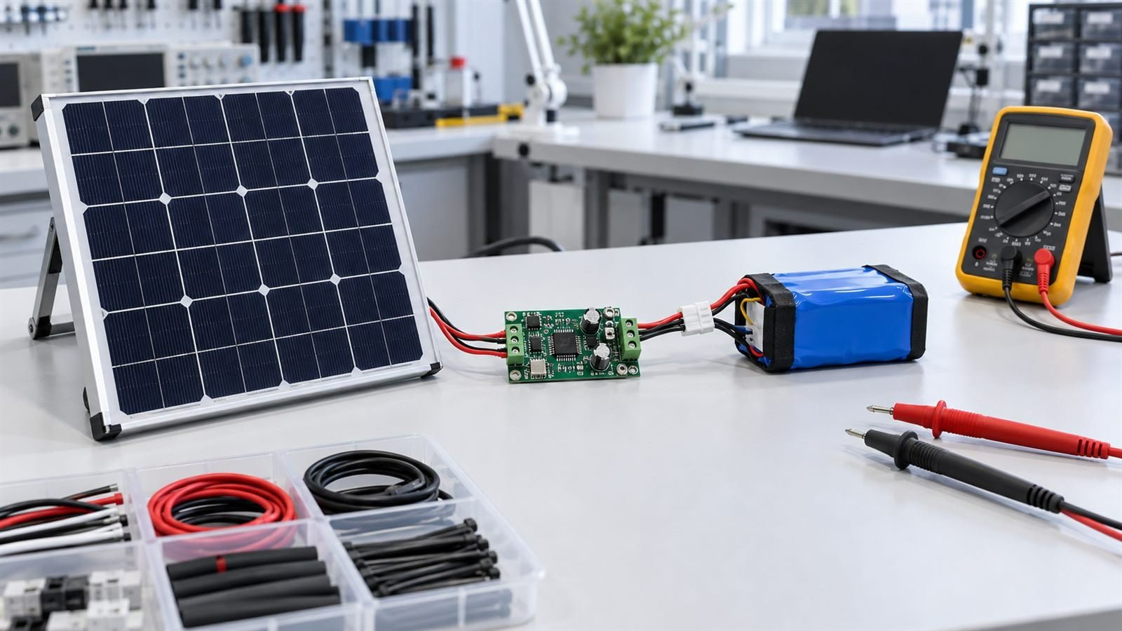
Identify the exact charging IC or solar power-management circuit. Review its minimum input voltage, cold-start requirement, operating input range, absolute maximum input voltage, quiescent current, charge profile, and any maximum-power-point behavior.
A nominal 3.7 V lithium-ion battery, for example, does not imply that any panel labeled near 3.7 V can charge it. The circuit needs voltage headroom and must follow the correct battery charging profile. The module should never be connected directly to a rechargeable lithium battery without suitable charge control and protection.
Allow for Voltage Changes With Light
Under weak illumination, available current falls substantially and the loaded operating voltage may also move. A charger that works on a bright bench can stop harvesting energy in realistic shade or cloud conditions.
Define the minimum useful light condition for the product. Measure whether the circuit starts, remains in regulation, and delivers net charge after its own standby consumption is included.
Allow for Temperature
Silicon module voltage changes with cell temperature. The design must check both hot operation and the highest expected open-circuit voltage under cold conditions. Use the proposed module’s verified electrical behavior and the charger’s input limits rather than relying on a generic percentage.
The enclosure can make the cells hotter than ambient air, especially when the panel is bonded to a dark housing. Test the assembled product in representative sunlight and airflow.
Determine the Required Daily Energy
Voltage compatibility only confirms that charging is possible. The panel must also replace the device’s daily energy use after losses. Measure sleep, sensing, processing, radio, display, and actuator consumption across a complete duty cycle.
Then account for charging efficiency, battery losses, regulator losses, cable loss, temperature, orientation, shading, and weather. The detailed IoT solar panel sizing guide explains how to build this energy balance.
Choose Series and Parallel Cell Configuration
Connecting more cell sections in series raises module voltage. Increasing active area in parallel increases current. In a compact panel, these choices compete for the same physical space.
A high-voltage configuration may use many narrow series sections and produce less current than a lower-voltage arrangement using the same area. The supplier should propose a cell map that meets the charging circuit’s operating range without wasting excessive active area. The related guide on small solar panel cell layout explains how series connections, current paths, inactive borders, and shadow sensitivity interact.
Check Startup and Recovery Behavior
A system can operate normally once the battery has charge but fail after deep discharge. Test cold start with the storage device at its lowest permitted state, under the minimum expected light. Observe whether the charger repeatedly attempts to start and collapses the panel voltage.
Also measure recovery after several low-sun days. A system with a large battery may take a long time to return to its normal state if the module provides only a small daily surplus.
Consider Partial Shading
Small modules are often installed near housing edges, antennas, straps, brackets, or covers. Partial shade can reduce the current of a series string and move the operating point outside the charger’s preferred window.
Show likely shadow patterns on the mechanical drawing. Test unfavorable orientation, narrow shadows, dirt, and realistic installation error. Do not validate only with the panel aimed directly at the sun.
Account for Cable and Connector Losses
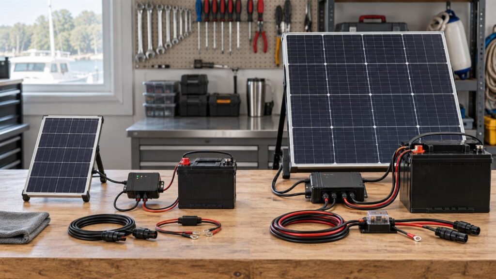
Long, thin conductors create voltage drop. Contact resistance, connector quality, polarity, and cable strain also affect system behavior. For a low-power product, a small loss can consume a meaningful part of the available energy.
Specify conductor size, cable length, connector part number, and mating interface. Test voltage at the charger input rather than only at the module terminals.
What to Send a Custom Module Supplier
- Battery chemistry, nominal voltage, capacity, and series configuration
- Charging IC and complete power-path diagram
- Minimum, preferred, and maximum charger input voltage
- Measured daily energy and peak current
- Required autonomy and recovery target
- Available module dimensions and active area
- Operating temperature and expected light conditions
- Cable length, connector, and polarity
- Likely shading and installation orientation
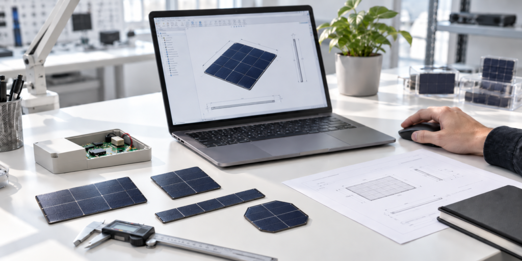
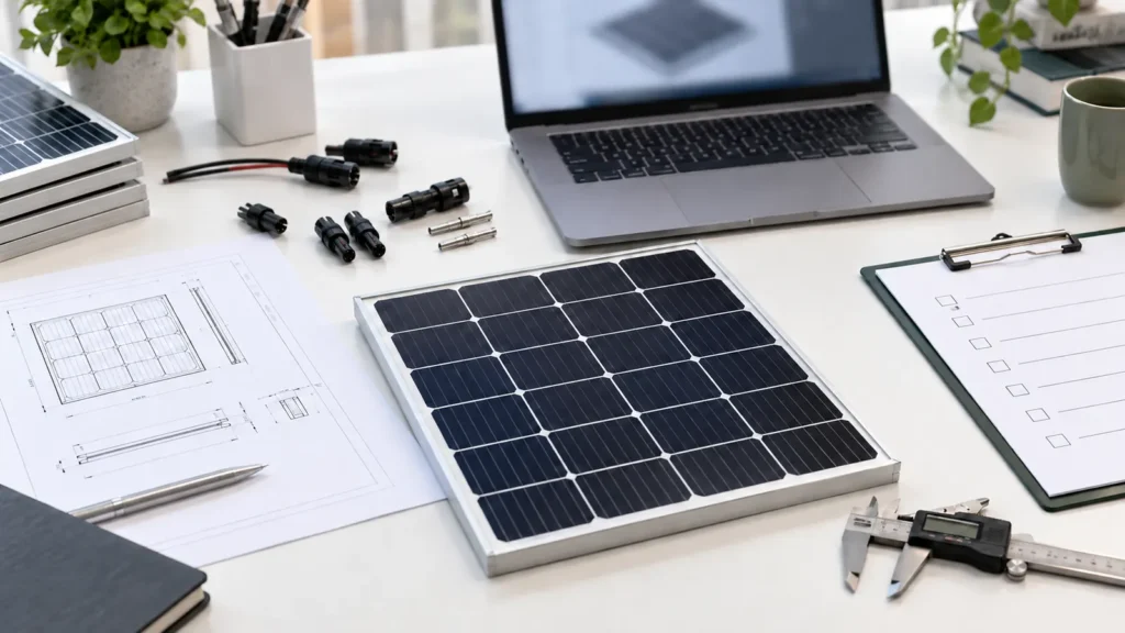
These inputs allow the manufacturer to propose Vmp, Imp, Voc, Isc, and a cell arrangement for the available area. The available outline still limits how much active cell area can be used, so confirm the envelope using the custom-size solar panel specification guide. Our small custom solar panels can be configured around product-level electrical and mechanical requirements.
Prototype Test Plan
Before testing, convert the electrical requirements into measurable acceptance criteria. Record the charger input-voltage window, the maximum permitted module Voc at the cold condition, the minimum useful charging current at the agreed low-light condition, and the expected net daily energy. Also define how the product should behave when light returns after the battery reaches its lowest allowed state.
These criteria should be tied to the assembled product and its intended orientation. A sample should not pass merely because its label voltage matches the requirement or because it charges under one bright lamp. The purpose of the prototype is to prove that the complete path remains inside safe limits and recovers reliably across the agreed operating conditions.
- Confirm polarity and open-circuit voltage before connection.
- Measure the operating point with the actual charger.
- Test at typical and minimum expected illumination.
- Evaluate hot cells and the coldest expected condition.
- Test startup from a low storage state.
- Measure daily harvested and consumed energy.
- Repeat across several unfavorable days.
- Test shading, cable drop, and installation tolerances.
Frequently Asked Questions
What panel voltage is needed for a 3.7 V lithium battery?
There is no universal value. It depends on the charging IC’s input range, required headroom, cell temperature, light conditions, and module operating voltage.
Can a 6 V panel charge a 3.7 V battery?
It may be suitable with an appropriate charging circuit, but the charger’s maximum input rating and the panel’s Voc must be checked.
Is higher panel voltage always better?
No. Excess voltage can exceed circuit limits or consume area that could otherwise provide more current. The design should target the useful operating window.
Why does the panel voltage collapse when connected?
The load may be demanding more current than the module can provide under that light condition, or the charger may not be controlling its input appropriately.
Should I size from watts or watt-hours?
Use daily energy in watt-hours for energy balance, then verify instantaneous power, voltage, and peak-current behavior separately.
Validate the Complete Charging Path
Reliable solar charging comes from matching the module, charger, storage device, load, and installation environment. Select voltage from the circuit requirements, size energy from the measured duty cycle, and verify both under realistic conditions.
Review the custom solar panel development process, our solar battery charger and maintainer solutions, and relevant solar application examples. To evaluate a battery, charging circuit, and available panel area, talk to our engineering team.